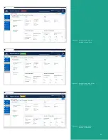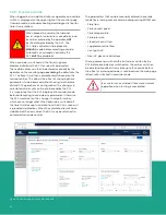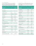
Figure 19 shows the web console
settings for an air assist flare
configuration where the air flow
can be varied continuously. While
majority of these parameters are
like those under the steam assist
settings, the only differences are
the following:
• Minimum air flow
• Maximum air flow
This figure also shows as a
representative example the state
of the web console prior to clicking
either “CANCEL” or “SAVE and
CONTINUE” at the bottom. One of
these must be clicked for any of
the other tabs to be available.
Figure 20 shows the web console
settings for the discrete (3-speed)
air assist configuration with the
following settings:
• Low air flow
• Medium air flow
• High air flow
Figure 19: Flare settings for air assist (continuous)
Figure 20: Flare settings for air assist (discrete)
22
Содержание flare.IQ Generation 2
Страница 1: ...flare IQ Generation 2 Operation and maintenance manual...
Страница 2: ...2...
Страница 3: ...flare IQ Generation 2 Operation and maintenance manual 910 350 rev A June 2020 3...
Страница 4: ...no content intended for this page 4...
Страница 38: ...Figure 30 System wiring diagram 38...
Страница 48: ...48...
Страница 49: ...no content intended for this page 49...


