4
Chapter 1
Special Keys and Controls
•
Keyboard
•
103-/104-/107-key Packard Bell FineTip keyboard with independent standard numeric
keypad, international language support
•
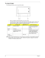
Touchpad
•
Multi-gesture touchpad, supporting two-finger scroll, pinch, rotate, flip
•
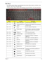
Media keys
•
Media control keys (printed on keyboard): play/pause, stop, previous, next
•
Dedicated volume up, volume down, mute keys
•
Control keys
•
Packard Bell Social Networks key
•
Packard Bell MyBackup key (Fn+F1)
•
Communication key (Fn + F2)
I/O Interface
•
2-in-1 card reader
•
Three USB 2.0 ports
•
HDMI™ port with HDCP support
•
External display (VGA) port
•
Headphone/speaker/line-out jack
•
Microphone-in jack
•
Ethernet (RJ-45) port
•
DC-in jack for AC adapter
Software
•
Productivity
•
Packard Bell MyBackup Solution
•
Packard Bell Optical Drive Power Management (for models with ODD eject button)
•
Packard Bell Recovery Management
•
Packard Bell Social Networks
•
Adobe® Flash® Player 10
•
Adobe® Reader® 9.1
•
Google Toolbar™
•
Microsoft® Office 2010 preloaded (purchase a product key to activate)
•
Microsoft® Office Starter 2010
•
Security
•
Norton Internet Security™ 2010
•
Multimedia
•
Adobe® Photoshop® Elements 7
•
Cyberlink® PowerDVD™
•
Nero 9 Essentials
•
Gaming
Содержание ENTK83 Series
Страница 6: ...VI...
Страница 10: ...X Table of Contents...
Страница 38: ...28 Chapter 1...
Страница 55: ...Chapter 2 45...
Страница 56: ...46 Chapter 2...
Страница 71: ...Chapter 3 61 4 Detach the WLAN module from the WLAN socket...
Страница 88: ...78 Chapter 3 5 Lift the Bluetooth cable from the cable guides Discrete UMA...
Страница 99: ...Chapter 3 89 8 Remove the LCD assembly from the lower cover...
Страница 105: ...Chapter 3 95 5 Disconnect the inverter board cable going to the LVDS cable 6 Lift the inverter board from the LCD cover...
Страница 110: ...100 Chapter 3 5 Lift the microphone set clear of the panel...
Страница 116: ...106 Chapter 3 4 Replace the adhesive tape securing the microphone cable and the antenna together...
Страница 121: ...Chapter 3 111 4 Replace the adhesive tape securing the inverter board cable to the LCD cover...
Страница 122: ...112 Chapter 3 Replacing the Camera Module 1 Place the camera module in the LCD cover 2 Connect the camera cable...
Страница 127: ...Chapter 3 117 7 Replace the adhesive tape to secure the antennas to the lower cover...
Страница 138: ...128 Chapter 3 4 Connect the USB cable to the mainboard and lock the connector...
Страница 144: ...134 Chapter 3 Replacing the Upper Cover 1 Place the upper cover on the lower cover as shown...
Страница 145: ...Chapter 3 135 2 Connect the following three 3 cables to the mainboard 3 Connect and lock the power board FFC A A B C...
Страница 146: ...136 Chapter 3 4 Connect the speaker cable B 5 Connect and lock the touchpad FFC C...
Страница 148: ...138 Chapter 3 Replacing the RTC Battery UMA Only 1 Place the RTC battery into the mainboard connector...
Страница 150: ...140 Chapter 3 4 Slide the HDD module in the direction of the arrow to connect the interface...
Страница 160: ...150 Chapter 3...
Страница 188: ...178 Chapter 5...
Страница 219: ...Chapter 6 209...
Страница 228: ...Appendix A 200...
Страница 236: ...208 Appendix C...
Страница 240: ...212...


