Chapter 3
123
4.
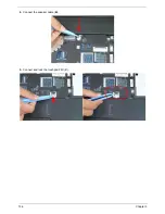
Place the mainboard in the chassis, left edge first to line up the I/O ports.
NOTE:
Ensure the I/O ports are positioned correctly through the casing.
5.
UMA: Replace the three (3) screws to secure the mainboard.
Discrete: Replace the one (1) screw to secure the mainboard.
Discrete
UMA
Step
Size
Quantity
Screw Type
Mainboard
M2.5*5 (red callouts)
1
(UMA Only)
M2.5*5 (green
callouts)
2
Содержание ENTK83 Series
Страница 6: ...VI...
Страница 10: ...X Table of Contents...
Страница 38: ...28 Chapter 1...
Страница 55: ...Chapter 2 45...
Страница 56: ...46 Chapter 2...
Страница 71: ...Chapter 3 61 4 Detach the WLAN module from the WLAN socket...
Страница 88: ...78 Chapter 3 5 Lift the Bluetooth cable from the cable guides Discrete UMA...
Страница 99: ...Chapter 3 89 8 Remove the LCD assembly from the lower cover...
Страница 105: ...Chapter 3 95 5 Disconnect the inverter board cable going to the LVDS cable 6 Lift the inverter board from the LCD cover...
Страница 110: ...100 Chapter 3 5 Lift the microphone set clear of the panel...
Страница 116: ...106 Chapter 3 4 Replace the adhesive tape securing the microphone cable and the antenna together...
Страница 121: ...Chapter 3 111 4 Replace the adhesive tape securing the inverter board cable to the LCD cover...
Страница 122: ...112 Chapter 3 Replacing the Camera Module 1 Place the camera module in the LCD cover 2 Connect the camera cable...
Страница 127: ...Chapter 3 117 7 Replace the adhesive tape to secure the antennas to the lower cover...
Страница 138: ...128 Chapter 3 4 Connect the USB cable to the mainboard and lock the connector...
Страница 144: ...134 Chapter 3 Replacing the Upper Cover 1 Place the upper cover on the lower cover as shown...
Страница 145: ...Chapter 3 135 2 Connect the following three 3 cables to the mainboard 3 Connect and lock the power board FFC A A B C...
Страница 146: ...136 Chapter 3 4 Connect the speaker cable B 5 Connect and lock the touchpad FFC C...
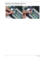
Страница 148: ...138 Chapter 3 Replacing the RTC Battery UMA Only 1 Place the RTC battery into the mainboard connector...
Страница 150: ...140 Chapter 3 4 Slide the HDD module in the direction of the arrow to connect the interface...
Страница 160: ...150 Chapter 3...
Страница 188: ...178 Chapter 5...
Страница 219: ...Chapter 6 209...
Страница 228: ...Appendix A 200...
Страница 236: ...208 Appendix C...
Страница 240: ...212...


