22
Chapter 1
Audio Subsystem
Graphics Controller
Video Interface
VRAM
Item
Specification
Audio Codec
Chipset
Realtek ALC272
Package
48pin LQFP
Speaker Amplifier
TPA6017A2_TSSOP20
Audio Port
Internal
1 mic, 1 speaker
Compatibility
Dolby® Digital Live, DTS® CONNECT™, Dolby® Home Theater, and SRS®
programs
Sampling Rate
44.1k/48k/96k/192kHz
External
Mic jack
Headphone jack
Item
Specification
Discrete
UMA
VGA Chip
ATI Mobility Radeon™ HD 5650/5470 GPU
On Board 1024MB(5650) / 512MB(5470) DDR3 Video RAM
N/A
Supports
•
PCI Express 2.1 x16 bus interface
•
DirectX® 11 support
•
OpenGL 3.2 support
•
Image quality enhancement technology
•
ATI Eyefinity multi-display technology
•
ATI Stream acceleration technology
•
ATI Avivo HD Video & Display technology
•
Certified drivers for Windows 7, Windows Vista, and
Windows XP
•
Engine clock speed: 550 MHz / 750 MHz
•
Memory clock speed: 800 MHz
•
VGA output support
•
HDMI output Support
N/A
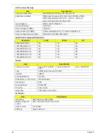
Item
Specification
Chipset
ATI Mobility Radeon™ HD 5650/5470 GPU
Package
uFCBGA-962
Interface
LVDS / CRT / HDMI
Compatibility
1366x768/60Hz 16:9 / 1360x768/60Hz 16:9 / 1280x768/60Hz 16:10 / 1280x720/
60Hz 16:9 / 1280x600/60Hz 16:9 / 1024x768p/60Hz 4:3 / 800x600p/60Hz 4:3
Sampling rate
60Hz / 59Hz / 30Hz
Item
Specification
Discrete
UMA
Chipset
ATI Mobility Radeon™ HD 5650/
5470 GPU
N/A
Memory size
512MB / 1024MB
N/A
Interface
DDR3
N/A
Содержание ENTK83 Series
Страница 6: ...VI...
Страница 10: ...X Table of Contents...
Страница 38: ...28 Chapter 1...
Страница 55: ...Chapter 2 45...
Страница 56: ...46 Chapter 2...
Страница 71: ...Chapter 3 61 4 Detach the WLAN module from the WLAN socket...
Страница 88: ...78 Chapter 3 5 Lift the Bluetooth cable from the cable guides Discrete UMA...
Страница 99: ...Chapter 3 89 8 Remove the LCD assembly from the lower cover...
Страница 105: ...Chapter 3 95 5 Disconnect the inverter board cable going to the LVDS cable 6 Lift the inverter board from the LCD cover...
Страница 110: ...100 Chapter 3 5 Lift the microphone set clear of the panel...
Страница 116: ...106 Chapter 3 4 Replace the adhesive tape securing the microphone cable and the antenna together...
Страница 121: ...Chapter 3 111 4 Replace the adhesive tape securing the inverter board cable to the LCD cover...
Страница 122: ...112 Chapter 3 Replacing the Camera Module 1 Place the camera module in the LCD cover 2 Connect the camera cable...
Страница 127: ...Chapter 3 117 7 Replace the adhesive tape to secure the antennas to the lower cover...
Страница 138: ...128 Chapter 3 4 Connect the USB cable to the mainboard and lock the connector...
Страница 144: ...134 Chapter 3 Replacing the Upper Cover 1 Place the upper cover on the lower cover as shown...
Страница 145: ...Chapter 3 135 2 Connect the following three 3 cables to the mainboard 3 Connect and lock the power board FFC A A B C...
Страница 146: ...136 Chapter 3 4 Connect the speaker cable B 5 Connect and lock the touchpad FFC C...
Страница 148: ...138 Chapter 3 Replacing the RTC Battery UMA Only 1 Place the RTC battery into the mainboard connector...
Страница 150: ...140 Chapter 3 4 Slide the HDD module in the direction of the arrow to connect the interface...
Страница 160: ...150 Chapter 3...
Страница 188: ...178 Chapter 5...
Страница 219: ...Chapter 6 209...
Страница 228: ...Appendix A 200...
Страница 236: ...208 Appendix C...
Страница 240: ...212...


