170
Chapter 5
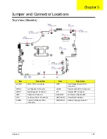
Bottom View (Discrete)
Item
Description
Item
Description
PJP2
Battery connector
JHP1
External SPDIF connector
PJP1
DC-IN jack
JBT1
Bluetooth connector
JDIMM1/
JDIMM2
DDR3 memory socket
JHDD1
SATAHDD connector
JCRT1
External CRT connector
JODD1
SATAODD connector
JRJ45
RJ45 LAN
JFAN1
FAN connector
JHDMI1
HDMI connector
JCPU1
CPU socket
JMINI1
WLAN connector
U3
NB RS880M
JUSB1
USB connector
U5
VGA
JMIC1
External microphone connector
U41
PCH
Содержание ENTK83 Series
Страница 6: ...VI...
Страница 10: ...X Table of Contents...
Страница 38: ...28 Chapter 1...
Страница 55: ...Chapter 2 45...
Страница 56: ...46 Chapter 2...
Страница 71: ...Chapter 3 61 4 Detach the WLAN module from the WLAN socket...
Страница 88: ...78 Chapter 3 5 Lift the Bluetooth cable from the cable guides Discrete UMA...
Страница 99: ...Chapter 3 89 8 Remove the LCD assembly from the lower cover...
Страница 105: ...Chapter 3 95 5 Disconnect the inverter board cable going to the LVDS cable 6 Lift the inverter board from the LCD cover...
Страница 110: ...100 Chapter 3 5 Lift the microphone set clear of the panel...
Страница 116: ...106 Chapter 3 4 Replace the adhesive tape securing the microphone cable and the antenna together...
Страница 121: ...Chapter 3 111 4 Replace the adhesive tape securing the inverter board cable to the LCD cover...
Страница 122: ...112 Chapter 3 Replacing the Camera Module 1 Place the camera module in the LCD cover 2 Connect the camera cable...
Страница 127: ...Chapter 3 117 7 Replace the adhesive tape to secure the antennas to the lower cover...
Страница 138: ...128 Chapter 3 4 Connect the USB cable to the mainboard and lock the connector...
Страница 144: ...134 Chapter 3 Replacing the Upper Cover 1 Place the upper cover on the lower cover as shown...
Страница 145: ...Chapter 3 135 2 Connect the following three 3 cables to the mainboard 3 Connect and lock the power board FFC A A B C...
Страница 146: ...136 Chapter 3 4 Connect the speaker cable B 5 Connect and lock the touchpad FFC C...
Страница 148: ...138 Chapter 3 Replacing the RTC Battery UMA Only 1 Place the RTC battery into the mainboard connector...
Страница 150: ...140 Chapter 3 4 Slide the HDD module in the direction of the arrow to connect the interface...
Страница 160: ...150 Chapter 3...
Страница 188: ...178 Chapter 5...
Страница 219: ...Chapter 6 209...
Страница 228: ...Appendix A 200...
Страница 236: ...208 Appendix C...
Страница 240: ...212...


