18
Chapter 1
CPU Fan True Value Table (TJ100) (Discrete Model)
Throttling 50%: On= 95°C; OFF=85°C
OS shut down at 100°C; H/W shut down at 92°C
CPU Fan True Value Table (TJ100) (UMA Model)
Throttling 50%: On= 95°C; OFF=85°C
OS shut down at 100°C; H/W shut down at 92°C
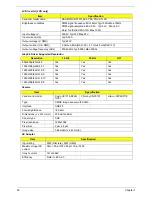
BIOS
CPU Temperature
Fan Speed (RPM)
SPL Spec (dBA)
Core
50
2500
28
56
2900
31
63
3200
34
70
3600
37
80
4000
40
95
4000
40
CPU Temperature
Fan Speed (RPM)
SPL Spec (dBA)
Core
50
2500
28
56
2900
31
63
3200
34
70
3600
37
80
4000
40
95
4000
40
Item
Specification
BIOS vendor
Insyde BIOS
BIOS Version
Flash
BIOS ROM type
16 Mbit (2MB)
BIOS ROM size
2MB
Support protocol
•
16Mbit(2MB) CMOS Serial Flash ROM
•
Support Acer UI
•
Support multi-boot
•
Suspend to RAM (S3)/Disk (S4)
•
Various hot-keys for system control
•
Support SMBIOS 2.3, PCI2.2.
•
Refer to Acer BIOS specification.
•
DMI utility for BIOS serial number configurable/asset tag
•
Support PXE
•
Support Y2K solution
•
Support WinFlash
•
Wake on LAN from S3
•
Wake on LAN form S4 in AC mode
•
System information
Содержание ENTK83 Series
Страница 6: ...VI...
Страница 10: ...X Table of Contents...
Страница 38: ...28 Chapter 1...
Страница 55: ...Chapter 2 45...
Страница 56: ...46 Chapter 2...
Страница 71: ...Chapter 3 61 4 Detach the WLAN module from the WLAN socket...
Страница 88: ...78 Chapter 3 5 Lift the Bluetooth cable from the cable guides Discrete UMA...
Страница 99: ...Chapter 3 89 8 Remove the LCD assembly from the lower cover...
Страница 105: ...Chapter 3 95 5 Disconnect the inverter board cable going to the LVDS cable 6 Lift the inverter board from the LCD cover...
Страница 110: ...100 Chapter 3 5 Lift the microphone set clear of the panel...
Страница 116: ...106 Chapter 3 4 Replace the adhesive tape securing the microphone cable and the antenna together...
Страница 121: ...Chapter 3 111 4 Replace the adhesive tape securing the inverter board cable to the LCD cover...
Страница 122: ...112 Chapter 3 Replacing the Camera Module 1 Place the camera module in the LCD cover 2 Connect the camera cable...
Страница 127: ...Chapter 3 117 7 Replace the adhesive tape to secure the antennas to the lower cover...
Страница 138: ...128 Chapter 3 4 Connect the USB cable to the mainboard and lock the connector...
Страница 144: ...134 Chapter 3 Replacing the Upper Cover 1 Place the upper cover on the lower cover as shown...
Страница 145: ...Chapter 3 135 2 Connect the following three 3 cables to the mainboard 3 Connect and lock the power board FFC A A B C...
Страница 146: ...136 Chapter 3 4 Connect the speaker cable B 5 Connect and lock the touchpad FFC C...
Страница 148: ...138 Chapter 3 Replacing the RTC Battery UMA Only 1 Place the RTC battery into the mainboard connector...
Страница 150: ...140 Chapter 3 4 Slide the HDD module in the direction of the arrow to connect the interface...
Страница 160: ...150 Chapter 3...
Страница 188: ...178 Chapter 5...
Страница 219: ...Chapter 6 209...
Страница 228: ...Appendix A 200...
Страница 236: ...208 Appendix C...
Страница 240: ...212...


