background image

Chapter 1

9

NOTE: 

1

 The front panel indicators are visible even when the computer cover is closed.

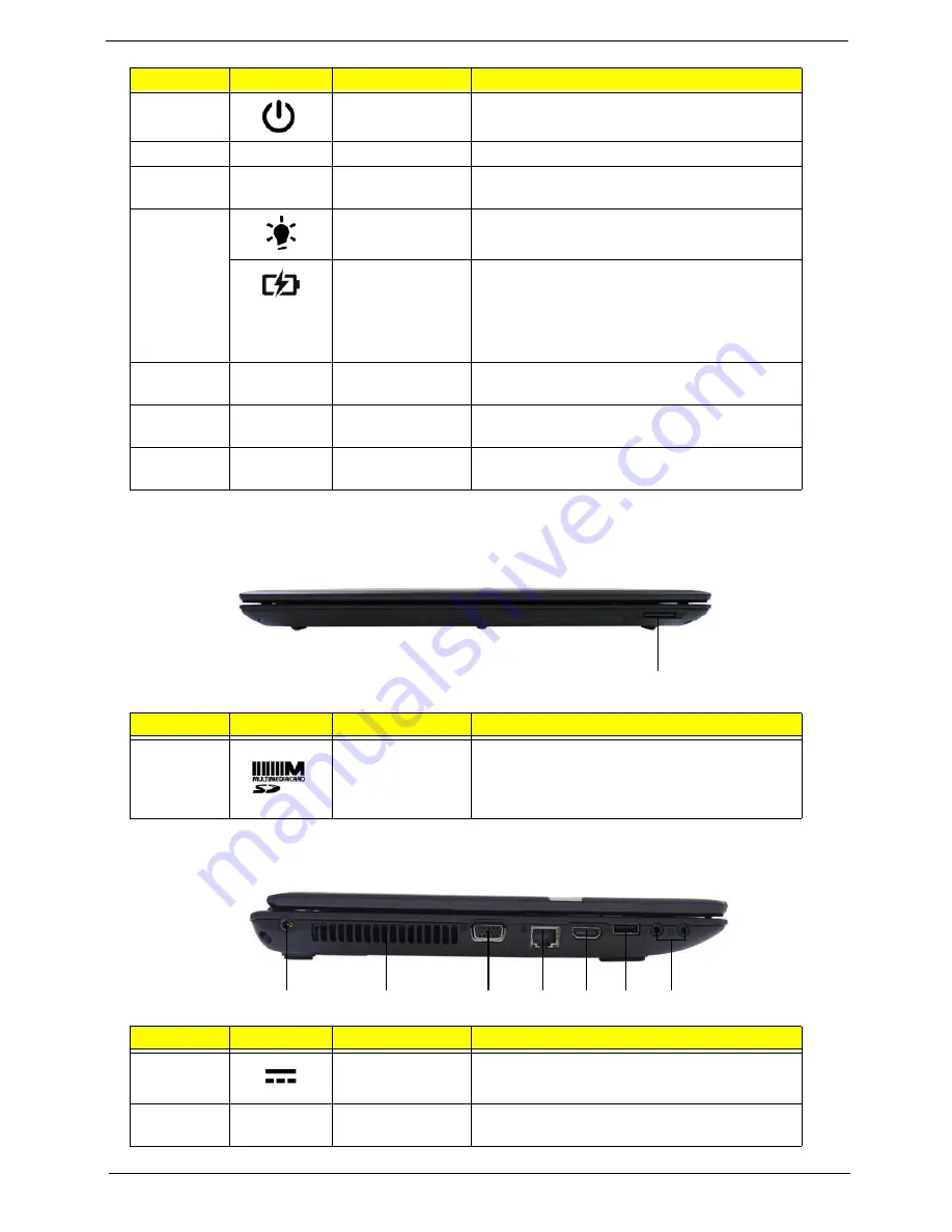
Closed Front View

Left View

5

Power button

Turns the computer on and off.

6

Keyboard

For entering data into your computer.

7

Palmrest

Comfortable support area for your hands when 
you use the computer.

8

Power

1

Indicates the computer’s power status.

Battery

1

Indicates the computer’s battery status.

1.

 Charging: The light shows amber when the 

battery is charging.

2. 

Fully charged: The light shows blue when in 

AC mode.

9

Click button 

The left and right buttons function like the left 
and right mouse buttons. 

10

Touchpad

Touch-sensitive pointing device which functions 
like a computer mouse.

11

Speakers

Left and right speakers deliver stereo audio 
output.

No.

Icon

Item

Description

1

2-in-1 card 
reader

Accepts Secure Digital (SD), MultiMediaCard 
(MMC)

Push to remove/install the card. Only one card 
can operate at any given time. 

No.

Icon

Item

Description

1

DC-in jack

Connects to an AC adapter

2

Ventilation slots

Enable the computer to stay cool, even after 
prolonged use.

No.

Icon

Item

Description

1

1

2

3

4

5

6

7

Содержание ENTK83 Series

Страница 1: ...Packard Bell ENTK81 83 Series Service Guide PRINTED IN TAIWAN Service guide files and updates are available on the ACER CSD web for more information please refer to http csd acer com tw...

Страница 2: ...II Revision History Please refer to the table below for the updates made on Packard Bell ENTK81 service guides Date Chapter Updates...

Страница 3: ...ations or warranties either expressed or implied with respect to the contents hereof and specifically disclaims any warranties of merchantability or fitness for any particular purpose Any Acer Incorpo...

Страница 4: ...MESSAGES Denotes actual messages that appear on screen NOTE Gives bits and pieces of additional information related to the current topic WARNING Alerts you to any damage that might result from doing...

Страница 5: ...NOT be covered in this generic service guide In such cases please contact your regional offices or the responsible personnel channel to provide you with further technical details 2 Please note WHEN OR...

Страница 6: ...VI...

Страница 7: ...ilities 37 DOS Flash Utility 38 WinFlash Utility 40 Remove HDD BIOS Password Utilities 41 Machine Disassembly and Replacement 47 Disassembly Requirements 47 Pre disassembly Instructions 48 Disassembly...

Страница 8: ...VDS Cable 107 Replacing the LCD Brackets 108 Replacing the LCD LED Panel 109 Replacing the Inverter Board LCD Only 110 Replacing the Camera Module 112 Replacing the LCD Bezel 113 Main Module Reassembl...

Страница 9: ...op View Discrete 169 Bottom View Discrete 170 Top View UMA 171 Bottom View UMA 172 Power Board Discrete 173 Power Board UMA 174 USB B Board 175 Card Reader Board Discrete only 175 Clearing Password Ch...

Страница 10: ...X Table of Contents...

Страница 11: ...B L2 cache 2 40 GHz 1066 MHz 25 W AMD Athlon II dual core processor P340 1 MB L2 cache 2 20 GHz 1066 MHz FSB 25 W N350 1 MB L2 cache 2 40 GHz 1066 MHz 35 W AMD V Series processor V140 512 KB L2 cache...

Страница 12: ...port up to 1920 x 1080 60 Hz MPEG 2 DVD decoding WMV9 VC 1 and H 264 AVC decoding Microsoft DirectX Video Acceleration DXVA application interface API 6 HDMI High Definition Multimedia Interface with...

Страница 13: ...cy Control BIOS user supervisor HDD passwords Kensington lock slot Power Subsystem ACPI 3 0 CPU power management standard supports Standby and Hibernation power saving modes Power adapter 3 pin 90 W A...

Страница 14: ...I O Interface 2 in 1 card reader Three USB 2 0 ports HDMI port with HDCP support External display VGA port Headphone speaker line out jack Microphone in jack Ethernet RJ 45 port DC in jack for AC adap...

Страница 15: ...Accessory Store Canada France Germany Italy Mexico Spain UK US only Packard Bell Identity Card Packard Bell InfoCentre Packard Bell Registration Packard Bell Updater Optional Items Bluetooth 3 0 HS 1...

Страница 16: ...16 x 16 EC I O Buffer Power Circuit uPGA 638 Package ATI RS880M BIOS HD Audio ATI SB820M ENE KB926 CMOS Camera RTC CKT USB port 9 3G GPS WWAN Option USB port 6 Card Reader Gen2 USB port 0 1 2 SATA HDD...

Страница 17: ...NE KB926 Bluetooth Conn RTC CKT S ATA SATA HDD Conn port 0 CMOS Camera USB port 0 1 2 USB SATA ODD FFC Conn Mini card WL X1 port 1 USB port 5 USB port 7 USB port 8 Dual Channel 204pin DDRIII SO DIMM X...

Страница 18: ...tion for selected models 2 Microphone Internal microphone for recording sound 3 Display screen Also called Liquid Crystal Display LCD displays computer output 4 HDD Indicates when the hard disk drive...

Страница 19: ...harging 2 Fully charged The light shows blue when in AC mode 9 Click button The left and right buttons function like the left and right mouse buttons 10 Touchpad Touch sensitive pointing device which...

Страница 20: ...l drive Internal optical drive accepts CDs or DVDs 3 Optical disk access indicator Lights up when the optical drive is active 4 Optical drive eject button Ejects the optical disk from the drive 5 Emer...

Страница 21: ...the computer s main memory 5 Battery lock Locks the battery in position 6 Ventilation slots and cooling fan Enable the computer to stay cool even after prolonged use Note Do not cover or obstruct the...

Страница 22: ...pad keep it and your fingers dry and clean The Touchpad is sensitive to finger movement hence the lighter the touch the better the response Tapping too hard will not increase the Touchpad s responsive...

Страница 23: ...r lock Windows function and special keys Lock Keys and embedded numeric keypad The keyboard has two lock keys which you can toggle on and off Lock key Description Caps Lock When Caps Lock is on all al...

Страница 24: ...ork domain M Minimizes all windows R Open the Run dialog box T Cycle through programs on the taskbar U Open Ease of Access Center X Open Windows Mobility Center BREAK Display the System Properties dia...

Страница 25: ...display output between the display screen external monitor if connected and both Fn F5 Display off Turns off the LCD back light Fn F6 Touchpad toggle Turns the touchpad on and off Fn F7 Play Pause Tog...

Страница 26: ...peed MT s Mfg Tech Cache Size Package Core Voltage Acer PN V140 1600 1 3200 45nm 512KB uPGA 638 0 8125 1 3125 KC V0002 140 P340 2200 2 3200 45nm 512KB 2 uPGA 638 0 8000 1 2000 KC AP002 340 N350 2400 2...

Страница 27: ...liance Item Specification Chipset AMD SB820M Package uFCBGA 605 Features Processor Interface A Link Express II interface to Northbridges PCI ExpressR Controller PCI Host Bus Controller USB Controllers...

Страница 28: ...an Speed RPM SPL Spec dBA Core 50 2500 28 56 2900 31 63 3200 34 70 3600 37 80 4000 40 95 4000 40 Item Specification BIOS vendor Insyde BIOS BIOS Version Flash BIOS ROM type 16 Mbit 2MB BIOS ROM size 2...

Страница 29: ...1024MB 2048MB 3072MB 2048MB 0MB 2048MB 2048MB 1024MB 3072MB 2048MB 2048MB 4096MB 2048MB 4096MB 6144MB 4096MB 4096MB 8192MB Item Specification LAN Chipset Broadcom 57780KMLG Support LAN protocol IEEE...

Страница 30: ...45016B9A300 Toshiba MK1665GSX Seagate ST9160314AS Western Digital WD2500BEVT 22A23T0 Hitachi HTS545025B9A300 Toshiba MK2565GSX Seagate ST9250315AS Western Digital WD3200BEVT 22A23T0 Hitachi HTS545032B...

Страница 31: ...nism Load Manual Release a Electrical Release Release Button b Release by ATAPI command c Emergency Release Power Requirement Input Voltage 5 V 5 Operating Item Specification Vendor model name HLDS BD...

Страница 32: ...port OpenGL 3 2 support Image quality enhancement technology ATI Eyefinity multi display technology ATI Stream acceleration technology ATI Avivo HD Video Display technology Certified drivers for Windo...

Страница 33: ...fication PCMCIA controller Supports card type Number of slots Access location Supports ZV Zoomed Video port Supports 32 bit CardBus Item Specification Discrete UMA Core logic AMD RS880M North Bridge u...

Страница 34: ...cursor keys Factory configurable different languages by OEM customer Item Specification I O support 2 in 1 card reader SD MMC Three USB 2 0 ports HDMI port External display VGA port Headphone speaker...

Страница 35: ...l Interface 1 channel LVDS Viewing Angle degree Horizontal Right CR 10 Left Vertical Upper CR 10 Lower 40 Right 40 Left 10 Upper 30 Lower Item Specification Vendor model name AUO B156XW01 V2 LG LP156W...

Страница 36: ...Typ 55Khz Max 65Khz Resolution 16 bits 32 bits ATI 800x600p 60Hz 4 3 Yes Yes Yes 1024x768p 60Hz 4 3 Yes Yes Yes 1280x600 60Hz 16 9 Yes Yes Yes 1280x720 60Hz 16 9 Yes Yes Yes 1280x768 60Hz 16 10 Yes Ye...

Страница 37: ...ff Amber color blinking S3 state Battery state Charging Amber solid on Battery charging with AC Blue color solid on Battery full Amber blinking Battery abnormal stop charge or batter in low power stat...

Страница 38: ...28 Chapter 1...

Страница 39: ...In this menu user can change boot device without entering BIOS SETUP Utility Navigating the BIOS Utility There are five menu options Information Main Security Boot and Exit Follow these instructions...

Страница 40: ...the system Manufacturer Name This field displays the manufacturer of this system UUID Universally Unique Identifier UUID is an identifier standard used in software construction standardized by the Op...

Страница 41: ...nables disables the system boot from LAN remote server Option Enabled or Disabled F12 Boot Menu Enables disables Boot Menu during POST Option Enabled or Disabled D2D Recovery Enables disables D2D Reco...

Страница 42: ...of parameters except the date and time N A Set User Password Press Enter to set the user password When user password is set this password protects the BIOS Setup Utility from unauthorized access The...

Страница 43: ...o Set 4 If desired you can opt to enable the Password on Boot parameter 5 When you are done press F10 to save the changes and exit the BIOS Setup Utility Removing a Password Follow these steps 1 Use t...

Страница 44: ...arameter 6 When you are done press F10 to save the changes and exit the BIOS Setup Utility If the verification is OK the screen will display as following The password setting is complete after the use...

Страница 45: ...the list or F6 to move it up the list Press Esc to escape the menu F1 ESC Help Exit Select Item Select Menu Change Values Select SubMenu Enter F9 F10 Setup Default Save and Exit Boot priority order 1...

Страница 46: ...values for all Setup items Discard Changes Load previous values for all Setup items Save Changes Save setup data Item Specific Help Exit System Setup and save your changes to CMOS F1 ESC Help Exit Se...

Страница 47: ...y Diskette before you use the flash utility NOTE Do not install memory related drivers XMS EMS DPMI when you use the flash NOTE Please use the AC adaptor power supply when you run the flash utility If...

Страница 48: ...ce then press F5 to move it down the list or F6 to move it up the list Press Esc to escape the menu F1 ESC Help Exit Select Item Select Menu Change Values Select SubMenu Enter F9 F10 Setup Default Sav...

Страница 49: ...e message Please do not remove AC Power Source displays NOTE If the AC power is not connected the following message displays Plug in the AC power to continue 5 Flash is complete when the message Flash...

Страница 50: ...40 Chapter 2 WinFlash Utility Perform the following steps to use the WinFlash Utility 1 Double click the WinFlash executable 2 Click OK to begin the update A progress screen displays...

Страница 51: ...is displayed select the Enter Unlock Password option on the screen 2 An Encode key is generated for unlocking utilities Note down this key 3 Execute the UnlockHD EXE file to create the unlock code in...

Страница 52: ...tal instrument to short the R334 point Cleaning BIOS Passwords To clean the User or Supervisor passwords perform the following steps 1 From a DOS prompt execute clnpwd exe 2 Press 1 or 2 to clean the...

Страница 53: ...ged without accessing the BIOS To use Boot Sequence Selector perform the following steps 1 Enter into DOS 2 Execute BS exe to display the usage screen 3 Select the desired boot sequence by entering th...

Страница 54: ...mber to eeprom max 22 characters dmitools wu xxxx Write uuid to eeprom dmitools wa xxxx Write asset tag to eeprom max 32 characters The following examples show the commands and the corresponding outpu...

Страница 55: ...Chapter 2 45...

Страница 56: ...46 Chapter 2...

Страница 57: ...oting Disassembly Requirements To disassemble the computer you need the following tools Wrist grounding strap and conductive mat for preventing electrostatic discharge Flat screwdriver Philips screwdr...

Страница 58: ...at you do the following 1 Turn off the power to the system and all peripherals 2 Unplug the AC adapter and all power and signal cables from the system NOTE Make sure you match the AC adapter with the...

Страница 59: ...bly LCD module disassembly The flowcharts provided in the succeeding disassembly sections illustrate the entire disassembly sequence Observe the order of the sequence to avoid damage to any of the har...

Страница 60: ...yboard you must first remove the switch board Screw List Step Screw Quantity Part No ODD Module M 2 5 8 1 86 R4F02 002 ODD Bracket M2 3 2 86 R4F02 007 3G Cover M2 5 8 1 86 R4F02 002 Lower Logic Door M...

Страница 61: ...rection shown 2 Slide and hold the battery release latch to the release position 1 then lift out the battery pack from the main unit 2 NOTE The battery has been highlighted with a yellow oval as shown...

Страница 62: ...52 Chapter 3 Removing the SD Dummy Card 1 Push the SD dummy card all the way in to eject it 2 Pull it out from the slot...

Страница 63: ...emoving the Keyboard 1 Unlock the six 6 keyboard locks 2 Pry up the center of the keyboard and rotate it upward away from the upper cover 3 Turn the keyboard over on to the touchpad area to expose the...

Страница 64: ...54 Chapter 3 4 Open the locking latch and disconnect the FPC from the mainboard 5 Lift the keyboard clear of the upper cover...

Страница 65: ...5 Removing the ODD Module 1 See Removing the Battery Pack on page 51 2 Remove the one 1 screw securing the ODD module 3 Pull the ODD module out from the chassis Step Size Quantity Screw Type ODD Modul...

Страница 66: ...move the two 2 screws securing the ODD bracket and remove the ODD bracket from the ODD module 5 Remove the ODD bezel by prying the top edge away and clear of the module Step Size Quantity Screw Type O...

Страница 67: ...Door 1 Remove two 2 screws from the logic lower door 2 Lift the door beginning from the inner edge as shown 3 Lift the door clear of the device exposing the HDD DIMM and WLAN modules Step Size Quantit...

Страница 68: ...Chapter 3 Removing the 3G Cover Discrete Only 1 Remove one 1 screw from the 3G cover 2 Lift the 3G cover from the right edge first then remove completely Step Size Quantity Screw Type 3G Cover M2 5 8...

Страница 69: ...Module 1 See Removing the Logic Lower Door on page 57 2 Push out the release latches on both sides of the DIMM socket to release the DIMM module 3 Remove the DIMM module 4 Repeat steps 2 and 3 for the...

Страница 70: ...on page 57 2 Disconnect the antenna cables from the WLAN module NOTE Cable placement is Black to the MAIN terminal and White to the AUX terminal 3 Move the antenna away and remove the one 1 screw to...

Страница 71: ...Chapter 3 61 4 Detach the WLAN module from the WLAN socket...

Страница 72: ...plastic tweezers lift the pull tab from the chassis 3 Using the pull tab slide the HDD module in the direction of the arrow to disconnect the interface 4 Lift the HDD module clear of the HDD bay NOTE...

Страница 73: ...Chapter 3 63 5 Remove the four 4 screws two each side securing the HDD to the carrier 6 Remove the HDD from the carrier Step Size Quantity Screw Type HDD Carrier M3 3 4...

Страница 74: ...64 Chapter 3 Removing the RTC Battery UMA Only 1 See Removing the Logic Lower Door on page 57 2 Using plastic tweezers lift the RTC battery from mainboard connector...

Страница 75: ...M2 5 5 3 86 R4F02 001 Thermal Module M1 98 3 4 86 R4F02 004 Thermal Module Discrete only M2 5 5 2 86 R4F02 001 LCD Module M2 5 8 4 86 R4F02 002 Remove Mainboard Remove Upper Cover Remove Power Board...

Страница 76: ...y Process on page 50 2 Turn the computer over Remove the twelve 12 screws on the lower cover and four 4 screws from the battery bay NOTE The lower cover may vary depending on your model Step Size Quan...

Страница 77: ...Chapter 3 67 3 Turn the computer over and disconnect the following three 3 cables from the mainboard 4 Unlock and disconnect the power board FFC A A B C...

Страница 78: ...Disconnect the speaker cable B 6 Unlock and disconnect the touchpad FFC C NOTE Avoid pulling on cables directly to prevent damage to the connectors NOTE Use the pull tabs on FFCs whenever available to...

Страница 79: ...shown 8 Starting at the bottom right side of the cover pry apart the upper and lower covers as shown Work along the front edge of the casing to the left as shown then lift the upper cover clear of th...

Страница 80: ...g the Speaker Module 1 See Removing the Upper Cover on page 66 2 Locate the speaker module on the upper cover as shown 3 Remove the speaker module cable from the cable guides 4 Lift the speaker module...

Страница 81: ...1 See Removing the Upper Cover on page 66 2 Remove two 2 screws from the power board 3 Turn the upper cover over and remove the power board cable Pass the cable through the upper cover as shown 4 Lif...

Страница 82: ...hpad board replace the entire upper cover 1 See Removing the Upper Cover on page 66 2 Remove the adhesive tape securing the touchpad FFC to the touchpad board 3 Lift the FFC to detach the adhesive sec...

Страница 83: ...Only 1 See Removing the Upper Cover on page 66 2 Remove both pieces of adhesive tape securing the FCC to the lower cover 3 Unlock the mainboard to card reader cable connector 4 Lift the FFC to detach...

Страница 84: ...74 Chapter 3 5 Remove one 1 screw from the card reader board 6 Lift the card reader board clear of the device Step Size Quantity Screw Type Card Reader Board M2 3 1...

Страница 85: ...over on page 66 2 See Removing the Card Reader Board Discrete Only on page 73 NOTE This procedure is only necessary for discrete models only 3 Unlock the mainboard to USB cable connector 4 Lift the FF...

Страница 86: ...3 5 Remove one 1 screw from the USB board NOTE The location of the bluetooth module may vary depending on your model 6 Lift the USB board clear of the lower cover Step Size Quantity Screw Type USB Bo...

Страница 87: ...oving the Upper Cover on page 66 2 See Removing the USB Board on page 75 NOTE This procedure is only necessary for discrete models only 3 Pry the Bluetooth board from the adhesive 4 Disconnect the mai...

Страница 88: ...78 Chapter 3 5 Lift the Bluetooth cable from the cable guides Discrete UMA...

Страница 89: ...apter 3 79 Removing the ODD Connector Board UMA Only 1 See Removing the Upper Cover on page 66 2 Unlock and disconnect the ODD FFC from the mainboard 3 Lift the ODD connector board from the lower cove...

Страница 90: ...the Mainboard 1 See Removing the Upper Cover on page 66 2 Disconnect the microphone cable from the mainboard 3 Disconnect the LVDS cable from the mainboard 4 Remove the LVDS cable and the DC IN cable...

Страница 91: ...ing screw from the mainboard CAUTION Do not remove the mainboard completely The mainboard is still connected to the chassis 6 To prevent damage lay the LCD panel flat and cover the panel as shown Disc...

Страница 92: ...d place it on a clean dust free surface CAUTION Do not use excessive force when turning the mainboard over as it is still connected to the chassis by the power cable 8 Disconnect the power cable 9 Rem...

Страница 93: ...Chapter 3 83 10 Remove the adhesive tape from the Bluetooth cable 11 Disconnect the Bluetooth cable from mainboard...

Страница 94: ...securing screws in reverse numerical order from screw 4 to 1 from the thermal module In the discrete model remove two 2 additional screws in reverse numerical order from screw 6 to 5 Discrete UMA Disc...

Страница 95: ...clear of the mainboard 5 Remove the adhesive tape securing the fan to the heatsink NOTE This procedure is only necessary for UMA models only 6 Remove the fan from the heatsink NOTE This procedure is...

Страница 96: ...it is not installed 1 See Removing the Thermal Module on page 84 2 Using a flat bladed screw driver rotate the CPU locking screw 180 counter clockwise as shown 3 Lift the CPU clear of the socket as sh...

Страница 97: ...emoving the Mainboard on page 80 2 Remove the adhesive tape securing the antennas to the lower cover 3 Free the microphone cable from the cable guides as shown 4 Free the black and white antenna cable...

Страница 98: ...oving the white antenna cable from the cable guides 6 Continue removing the black antenna cable from the cable guides 7 Remove four 4 screws from the LCD assembly Discrete UMA Step Size Quantity Screw...

Страница 99: ...Chapter 3 89 8 Remove the LCD assembly from the lower cover...

Страница 100: ...90 Chapter 3 Removing the DC IN Assembly 1 See Removing the LCD Assembly on page 87 2 Lift the DC IN cable from the lower cover 3 Lift the DC IN assembly from the lower cover...

Страница 101: ...02 003 Inverter Board LCD Only M2 5 5 1 86 R4F02 001 LCD LED Panel M2 5 5 4 86 R4F02 001 LCD Brackets M2 3 6 86 R4F02 007 Remove LCD LED Panel Remove LCD Bezel Remove LVDS Cable Remove LCD Module from...

Страница 102: ...the bottom edge of the bezel pry the bezel upwards and away from the panel Work along the side toward the top of the bezel prying the covers apart Continue along the top edge and down the other side t...

Страница 103: ...le 1 See Removing the LCD Bezel on page 92 2 Locate the camera module at the top of the LCD module and disconnect the camera cable 3 Lift the camera module from the adhesive on the LCD cover 4 Remove...

Страница 104: ...the LCD Bezel on page 92 2 Remove the adhesive tape securing the inverter board cable to the LCD cover 3 Remove one 1 screw from the inverter board 4 Disconnect the inverter board cable going to the...

Страница 105: ...Chapter 3 95 5 Disconnect the inverter board cable going to the LVDS cable 6 Lift the inverter board from the LCD cover...

Страница 106: ...l 1 See Removing the LCD Bezel on page 92 2 Remove the four 4 securing screws from the LCD LED panel 3 Remove the cable from the cable guide 4 Lift the LCD LED Panel clear of the module Step Size Quan...

Страница 107: ...ets 1 See Removing the LCD LED Panel on page 96 2 Remove the six 6 securing screws three on each side from the LCD brackets 3 Remove the LCD brackets by pulling away from the LCD panel Step Size Quant...

Страница 108: ...S cable 1 See Removing the LCD LED Panel on page 96 2 Remove the LVDS cable from the back of the panel 3 Peel back the mylar securing the LVDS cable 4 Disconnect the LVDS cable and remove it from the...

Страница 109: ...able 1 See Removing the LCD LED Panel on page 96 2 Remove the adhesive securing the microphone cable and antenna 3 Peel back the foil tabs and remove the microphone cable from the cable channel 4 Lift...

Страница 110: ...100 Chapter 3 5 Lift the microphone set clear of the panel...

Страница 111: ...tennas 1 See Removing the LCD LED Panel on page 96 2 Peel back the foil tabs securing the antenna to the LCD cover 3 Remove the cable from the cable guides 4 Using a flat plastic tool pry the antenna...

Страница 112: ...102 Chapter 3 5 Peel back the foil tabs securing the antenna to the LCD cover 6 Remove the white antenna from the cable guides 7 Using a flat plastic tool pry the antenna assembly clear of the device...

Страница 113: ...3 103 LCD Module Reassembly Procedure Replacing the Antennas 1 Adhere the white antenna assembly to the LCD cover 2 Run the cable along the cable guides 3 Fold over the foil tabs to secure the cable i...

Страница 114: ...104 Chapter 3 4 Adhere the black antenna assembly on the LCD cover 5 Run the cable along the cable channel 6 Fold over the foil tabs to secure the cable in place...

Страница 115: ...Run the cable along the cable channel IMPORTANT Ensure that the cable runs between the callouts to avoid trapping when the panel is replaced in the LCD module 3 Fold over the foil tabs and continue r...

Страница 116: ...106 Chapter 3 4 Replace the adhesive tape securing the microphone cable and the antenna together...

Страница 117: ...Chapter 3 107 Replacing the LVDS Cable 1 Place the LVDS cable onto the back of the panel 2 Connect the LVDS cable to the panel 3 Replace the mylar to secure the LVDS cable LCD LED LCD LED LCD LED...

Страница 118: ...ter 3 Replacing the LCD Brackets 1 Replace the LCD brackets to the LCD panel 2 Replace the six 6 securing screws three on each side to the LCD panel brackets Step Size Quantity Screw Type LCD Brackets...

Страница 119: ...the LCD LED Panel 1 Place the LCD panel in the LCD cover 2 Run the cable along the guide in the LCD cover as shown 3 Replace the four 4 securing screws to the LCD panel Step Size Quantity Screw Type...

Страница 120: ...ect the inverter board cable going to the LVDS cable 2 Connect the inverter board cable going to the LCD panel 3 Place the inverter board onto the LCD cover and replace one 1 screw from the inverter b...

Страница 121: ...Chapter 3 111 4 Replace the adhesive tape securing the inverter board cable to the LCD cover...

Страница 122: ...112 Chapter 3 Replacing the Camera Module 1 Place the camera module in the LCD cover 2 Connect the camera cable...

Страница 123: ...press down until there are no gaps between the bezel and the LCD cover IMPORTANT Ensure that the LCD cables pass through the hinge wells and are not trapped by the bezel 2 Replace the two 2 screws an...

Страница 124: ...114 Chapter 3 Main Module Reassembly Procedure Replacing the DC IN Assembly 1 Place the DC IN assembly into the lower cover 2 Place the DC IN cable into the lower cover as shown...

Страница 125: ...LCD Assembly 1 Place the LCD assembly on the lower cover 2 Replace four 4 screws to secure the LCD assembly 3 Place the black antenna cable into the cable guides Step Size Quantity Screw Type LCD Ass...

Страница 126: ...4 Place the white antenna cable into the cable guides 5 Continue replacing the black and white antenna cables into the cable guides as shown 6 Place the microphone cable into the cable guides as shown...

Страница 127: ...Chapter 3 117 7 Replace the adhesive tape to secure the antennas to the lower cover...

Страница 128: ...locator that must be positioned corresponding to the marker on the CPU socket 1 Place the CPU into the CPU socket as shown taking note of the Pin1 locator 2 Using a flat bladed screw driver rotate th...

Страница 129: ...HL Southbridge Laird T flex340 Laird T flex350 Eapus XR HL Northbridge Laird T flex740 Laird T flex350 1 Remove all traces of thermal grease from the CPU using a lint free cloth or cotton swab and Is...

Страница 130: ...to secure the fan to the heatsink NOTE This procedure is only necessary for UMA models only 5 Align the screw holes on the thermal module and mainboard then replace the module Keep the module as leve...

Страница 131: ...secure the thermal module in place In the discrete model replace two 2 additional screws in numerical order from screw 5 to 6 7 Connect the fan cable Discrete UMA Step Size Quantity Screw Type Thermal...

Страница 132: ...apter 3 Replacing the Mainboard 1 Connect the Bluetooth to mainboard cable 2 Apply the adhesive tape to secure the Bluetooth cable 3 Place the mainboard on a clean dust free surface Connect the power...

Страница 133: ...NOTE Ensure the I O ports are positioned correctly through the casing 5 UMA Replace the three 3 screws to secure the mainboard Discrete Replace the one 1 screw to secure the mainboard Discrete UMA Ste...

Страница 134: ...124 Chapter 3 6 Place the LVDS cable and the DC IN cable into the cable guide 7 Connect the LVDS cable to the mainboard 8 Connect the microphone cable to the mainboard...

Страница 135: ...Chapter 3 125 Replacing the ODD Connector Board UMA Only 1 Place the ODD connector board into the lower cover using the board pin 2 Connect the ODD FFC to the mainboard and lock the connector...

Страница 136: ...placing the Bluetooth Board 1 Place the Bluetooth cable into the cable guides 2 Connect the Bluetooth cable to the Bluetooth module 3 Place the Bluetooth board onto the adhesive Discrete UMA Discrete...

Страница 137: ...1 Place the USB board in the chassis NOTE The location of the bluetooth module may vary depending on your model 2 Secure the one 1 screw on the USB board 3 Adhere the FFC to the lower cover Step Size...

Страница 138: ...128 Chapter 3 4 Connect the USB cable to the mainboard and lock the connector...

Страница 139: ...ing the Card Reader Board Discrete Only 1 Place the card reader board in the device 2 Secure one 1 screw on the card reader board 3 Adhere the FFC to the lower cover Step Size Quantity Screw Type Card...

Страница 140: ...130 Chapter 3 4 Connect the card reader cable and lock the connector 5 Replace both pieces of adhesive tape to secure the FCC to the lower cover...

Страница 141: ...acing the Touchpad FFC 1 Connect the touchpad FFC to the connector and lock the FFC locking latch 2 Gently press on the FFC to adhere the cable to the upper cover 3 Replace the adhesive tape to secure...

Страница 142: ...del 1 Pass the cable through the upper cover as shown Turn the upper cover over and gently press down on the FFC to secure it to the upper cover 2 Place the power board onto the upper cover 3 Replace...

Страница 143: ...Chapter 3 133 Replacing the Speaker Module 1 Place the speaker module onto the upper cover 2 Place the speaker module cable into the cable guides as shown...

Страница 144: ...134 Chapter 3 Replacing the Upper Cover 1 Place the upper cover on the lower cover as shown...

Страница 145: ...Chapter 3 135 2 Connect the following three 3 cables to the mainboard 3 Connect and lock the power board FFC A A B C...

Страница 146: ...136 Chapter 3 4 Connect the speaker cable B 5 Connect and lock the touchpad FFC C...

Страница 147: ...computer over Replace the twelve 12 screws on the lower cover and four 4 screws in the battery bay NOTE The lower cover may vary depending on your model Step Size Quantity Screw Type Upper Cover M2 5...

Страница 148: ...138 Chapter 3 Replacing the RTC Battery UMA Only 1 Place the RTC battery into the mainboard connector...

Страница 149: ...the HDD Module 1 Place the HDD in the HDD carrier 2 Replace the four 4 screws two each side to secure the carrier 3 Insert the HDD module as indicated and lower it into place Step Size Quantity Screw...

Страница 150: ...140 Chapter 3 4 Slide the HDD module in the direction of the arrow to connect the interface...

Страница 151: ...to the WLAN socket 2 Replace the one 1 screw to secure the module 3 Connect the two 2 antenna cables to the module NOTE The black cable connects to the upper terminal MAIN and the white cable to the l...

Страница 152: ...142 Chapter 3 Replacing the DIMM Modules 1 Insert the DIMM module in place 2 Press down to lock the DIMM module in place 3 Repeat steps for the second DIMM module if present...

Страница 153: ...3 143 Replacing the 3G Cover Discrete Only 1 Line up the left edge of the 3G cover with the device and lower into place 2 Replace one 1 screw on the 3G cover Step Size Quantity Screw Type 3G Cover M2...

Страница 154: ...Lower Logic Door 1 Replace the lower logic door by first lining up the bottom edge and lowering the door into place 2 Replace two 2 screws to secure the lower logic door Step Size Quantity Screw Type...

Страница 155: ...ODD Module 1 Press the bezel into the tray bottom edge first to secure it to the ODD module 2 Place the bracket on the ODD module 3 Secure the ODD bracket with the two 2 screws Step Size Quantity Scr...

Страница 156: ...146 Chapter 3 4 Push the ODD module into the ODD bay until it is flush with the casing 5 Replace the one 1 screw to secure the module Step Size Quantity Screw Type ODD Module M2 5 8 1...

Страница 157: ...d 1 Place the keyboard face down on the palm rest 2 Connect the keyboard FPC to the mainboard and close the locking latch to secure the cable in place 3 Replace the keyboard by first lining up the bot...

Страница 158: ...148 Chapter 3 Replacing the SD Dummy Card 1 Insert the SD dummy card into the slot as shown 2 Push until the card clicks into place and is flush with the casing...

Страница 159: ...Replacing the Battery 1 Slide and hold the battery release latch to the release position 1 insert the battery pack and press down 2 2 Slide the battery lock in the direction shown to secure the batter...

Страница 160: ...150 Chapter 3...

Страница 161: ...by running the diagnostic test or by repeating the same operation 3 Use the following table with the verified symptom to determine which page to go to 4 If the Issue is still not resolved see Online...

Страница 162: ...extension cables between the computer and the outlet 3 Remove any surge protectors between the computer and the electrical outlet Plug the computer directly into a known good electrical outlet 4 Disc...

Страница 163: ...power see Power On Issue on page 152 3 Drain any stored power by removing the power cable and battery and holding down the power button for 10 seconds Reconnect the power and reboot the computer 4 Con...

Страница 164: ...e Resolution slider to the desired resolution e Click Apply and check the display Readjust if necessary 6 Roll back the video driver to the previous version if updated 7 Remove and reinstall the video...

Страница 165: ...e following actions one at a time to correct the problem Do not replace a non defective FRUs Built In Keyboard Failure If the built in Keyboard fails perform the following actions one at a time to cor...

Страница 166: ...perform the following actions one at a time to correct the problem Do not replace a non defective FRUs Internal Speaker Failure If the internal Speakers fail perform the following actions one at a tim...

Страница 167: ...Speaker Setup Follow the onscreen prompts to configure the speakers 8 Remove and recently installed hardware or software 9 Restore system and file settings from a known good date using System Restore...

Страница 168: ...o locate and resolve issues with the computer i When complete click Finish If an issue is discovered follow the onscreen information to resolve the problem 4 Run the Windows Memory Diagnostic Tool For...

Страница 169: ...eaks up or jumps Optical drive not found or not active Not shown in My Computer or the BIOS setup LED does not flash when the computer starts up The tray does not eject Access failure screen displays...

Страница 170: ...Movie fields select the desired player from the drop down menu 5 Check that the Regional Code is correct for the selected media IMPORTANT Region can only be changed a limited number of times After Cha...

Страница 171: ...rboard and cable connections c Try an alternate cable if available If the drive works with the new cable the original cable should be replaced 4 Reseat the drive ensuring and all cables are connected...

Страница 172: ...ls perform the following actions one at a time to correct the problem Do not replace a non defective FRUs Thermal Unit Failure If the Thermal Unit fails perform the following actions one at a time to...

Страница 173: ...is not fixed repeat the preceding steps and select an earlier time and date 9 Run the Event Viewer to check the events log for errors For more information see Windows Help and Support 10 Roll back th...

Страница 174: ...er a short circuit is suspected or whether the system is inoperative Follow these procedures to isolate the failing FRU do not isolate non defective FRU NOTE Verify that all attached devices are suppo...

Страница 175: ..._PEICORE SEC 0A Enter Boot Firmware Volume Functionality Name Include PostCode h Phase Post Code Description PEI_SIO_INIT PEI 70 Super I O Initialization PEI_CPU_REG_INIT PEI 71 CPU Early Initializati...

Страница 176: ...RIABLE_INIT_FAIL DXE 4C Fail to initial Variable Service DXE_MTC_INIT DXE 4D MTC Initial DXE_CPU_INIT DXE 4E CPU Middle Initialization DXE_MP_CPU_INIT DXE 4F Multi processor MiddleInitialization DXE_S...

Страница 177: ...BOOT_OPTION BDS 27 Get boot device information BDS_END_OF_BOOT_SELECTION BDS 28 End of boot selection BDS_ENTER_SETUP BDS 29 Enter Setup Menu BDS_ENTER_BOOT_MANAGER BDS 2A Enter Boot manager BDS_BOOT_...

Страница 178: ...Flash device in SMM SMM_SMM_PLATFORM_INIT SMM 0xA2 SMM service initial SMM_ACPI_ENABLE_START SMM 0xA6 OS call ACPI enable function SMM_ACPI_ENABLE_END SMM 0xA7 ACPI enable function complete SMM_S1_SLE...

Страница 179: ...Board FFC Connector JSPK2 Left Speaker Connector JLED2 Power board FFC Connector JSPK1 Right Speaker Connector JP1 Internal MIC Connector JKB1 Keyboard Connector SW2 SW3 Left button Right button JTP1...

Страница 180: ...DC IN jack JBT1 Bluetooth connector JDIMM1 JDIMM2 DDR3 memory socket JHDD1 SATAHDD connector JCRT1 External CRT connector JODD1 SATAODD connector JRJ45 RJ45 LAN JFAN1 FAN connector JHDMI1 HDMI connec...

Страница 181: ...connector JSPK2 Left Speaker connector JLED1 Powerboard FFC connector JSPK1 Right Speaker connector JMIC2 Internal MIC connector JKB1 Keyboard connector SW1 SW2 Left button Right button JTP1 Touch pad...

Страница 182: ...JP1 DC IN jack JBT1 BT with cable connector JDIMM1 JDIMM2 DDR3 memory socket JHDD1 SATA HDD connector JCRT1 D Sub connector JODD1 SATA ODD connector JRJ45 RJ45 of GLAN JFAN1 FAN connector JHDMI1 HDMI...

Страница 183: ...Board Discrete Item Description Item Description LED1 ON OFF LED LED9 N A LED2 ON OFF LED LED10 WLAN LED LED3 N A LED11 N A LED4 MEDIA LED LED12 N A LED5 N A SW1 Power BTN LED6 N A SW2 N A LED7 WWAN L...

Страница 184: ...er Board UMA Item Description Item Description LED1 ON OFF LED LED9 N A LED2 ON OFF LED LED10 WLAN LED LED3 N A LED11 N A LED4 MEDIA LED LED12 N A LED5 N A SW1 Power BTN LED6 N A SW2 N A LED7 WWAN LED...

Страница 185: ...Chapter 5 175 USB B Board Card Reader Board Discrete only Item Description JUSB1 JUSB2 USB Connector Item Description 1 Card reader PCB 2 Card reader connector 1 2...

Страница 186: ...e it is necessary to bypass the password check users need to short the HW Gap to clear the password by the following steps 1 Power Off the system and remove HDD AC and Battery from the machine 2 Disco...

Страница 187: ...orce the BIOS to enter a special BIOS block called Boot Block Steps for BIOS Recovery from USB Storage Before doing this prepare the Crisis USB key The Crisis USB key could be made by executing the Cr...

Страница 188: ...178 Chapter 5...

Страница 189: ...er reasons a part number change is made it will not be noted on the printed Service Guide For ACER AUTHORIZED SERVICE PROVIDERS your Acer office may have a DIFFERENT part number code from those given...

Страница 190: ...ription Acer Part No 1 Upper Cover 60 BQ502 001 6 HDD Door 42 R5202 001 2 Mainboard MB R4602 001 7 ODD Board 55 R4F02 003 3 Thermal Module 60 R5202 003 8 3G Door 42 R5202 002 4 USB Board 55 R5202 003...

Страница 191: ...Chapter 6 181 Upper Assembly No Description Acer Part No 1 Powerboard 55 R4F02 001 2 Touchpad FFC 50 R4F02 003 3 Upper Cover 60 BQ502 001 4 Speaker 23 R4F02 003 1 2 3 4...

Страница 192: ...rt No 1 LCD Bezel 60 BQ502 004 2 LCD Panel LK 1560D 013 3 LVDS cable w o camera 50 R4F02 008 4 LCD Brackets 33 R4F02 003 5 Camera 57 R4F02 001 6 LVDS cable w camera 50 R4F02 007 7 Inverter Board 19 R4...

Страница 193: ...o Description Acer Part No 1 LED Bezel 60 WSG02 003 2 LED Panel LK 15606 009 3 LVDS cable w o camera 50 R4F02 010 4 LED Brackets 33 R4F02 004 5 Camera 57 R4F02 001 6 LVDS cable 50 R4F02 009 7 LED Cove...

Страница 194: ...HP A0904A3 B1LF LV5 LED LF AP 0900A 005 BATTERY BATTERY SANYO AS10D LI ION 3S2P SANYO 6 CELL 4400MAH MAIN COMMON ID AS10D31 BT 00603 111 BATTERY SONY AS10D LI ION 3S2P SONY 6 CELL 4400MAH MAIN COMMON...

Страница 195: ...HM WN6603AH NI 23600 073 LITEON WIRELESS LAN REALTEK 8192SE BGN WN6603LH 2X2 BGN NI 23600 065 FOXCONN WIRELESS LAN ATHEROS HB97 2X2 BGN HM NI 23600 072 FOXCONN WIRELSS LAN ATHEROS HB95BG HM T77H121 10...

Страница 196: ...ISRAEL 3 PIN 27 TAVV5 012 POWER CORD INDIA 3 PIN 27 TAVV5 013 POWER CORD TWN 3 PIN 27 TAVV5 014 POWER CORD ARGENTINA 3 PIN 27 APV02 001 POWER CORD 3 PIN BRAZIL 27 SAD02 001 CASE COVER BRACKET ASSEMBLY...

Страница 197: ...NTHER B SATA LF F W C60F DISK IMBALANCE CRITERIA 0 014G CM KH 16007 026 HDD SEAGATE 2 5 5400RPM 250GB ST9250315AS 9HH132 189 WYATT WITH NEW PCB SATA 8MB LF F W 0001SDM1 KH 25001 019 HDD TOSHIBA 2 5 54...

Страница 198: ...al 17 Standard 103KS Black Arabic Texture KB I170G 172 Keyboard GATEWAY AC7T_G10B AC7T Internal 17 Standard 103KS Black Chinese Texture KB I170G 176 Keyboard GATEWAY AC7T_G10B AC7T Internal 17 Standar...

Страница 199: ...tandard 104KS Black FR Arabic Texture KB I170G 178 Keyboard GATEWAY AC7T_G10B AC7T Internal 17 Standard 104KS Black Nordic Texture KB I170G 186 Keyboard GATEWAY AC7T_G10B AC7T Internal 17 Standard 104...

Страница 200: ...TI DRIVE 12 7MM TRAY DL 8X AD 7585H LF W O BEZEL SATA HF WINDOWS 7 KU 0080E 027 ODD HLDS SUPER MULTI DRIVE 12 7MM TRAY DL 8X GT32N R5 2 LF W O BEZEL SATA WITH RENESAS SOLUTION PCC LD HF WINDOWS 7 KU 0...

Страница 201: ...15 6 W WXGA GLARE LTN156AT01 A01 LF 220NIT 8MS 600 1 LK 15606 001 CCFL LCD LPL 15 6 W WXGA GLARE LP156WH1 TLC1 LF 220NIT 16MS 400 1 LK 15608 013 LCD ASSY LCD MODULE 15 6 W WXGA GLARE W ANTENNA 2 CCD...

Страница 202: ...LF 220NIT 8MS 600 1 LK 15606 001 CCFL LCD LPL 15 6 W WXGA GLARE LP156WH1 TLC1 LF 220NIT 16MS 400 1 LK 15608 013 LCD ASSY LCD MODULE 15 6 W WXGA GLARE W ANTENNA 2 CCD 1 3M BLACK GTW 6M WSG02 001 LCD CO...

Страница 203: ...L LCD LPL 15 6 W WXGA GLARE LP156WH1 TLC1 LF 220NIT 16MS 400 1 LK 15608 013 LCD ASSY LCD MODULE 15 6 W WXGA GLARE W ANTENNA 2 CCD 1 3M RED GTW 6M WSX02 001 LCD COVER IMR RED GW 60 WSX02 001 LCD BEZEL...

Страница 204: ...0 1 LK 15608 013 LCD ASSY LED LCD MODULE 15 6 W WXGA GLARE W ANTENNA 2 CCD 1 3M BLACK PB 6M BQ502 003 LED LCD COVER IMR BLACK PB 60 BQ502 003 LCD BEZEL FOR W CMOS PB 60 BQ502 004 ANTENNA WLAN MAIN 50...

Страница 205: ...E LP156WH2 TLEA LF 220NIT 16MS 500 1 COLOR ENGINE LK 15608 011 LED LCD CPT 15 6 W WXGA GLARE CLAA156WB11A LF 220NIT 8MS 600 1 LK 1560A 004 LCD ASSY LED LCD MODULE 15 6 W WXGA GLARE W ANTENNA 2 CCD 1 3...

Страница 206: ...8MS 650 1 LK 1560D 010 LED LCD LPL 15 6 W WXGA GLARE LP156WH2 TLEA LF 220NIT 16MS 500 1 COLOR ENGINE LK 15608 011 LED LCD CPT 15 6 W WXGA GLARE CLAA156WB11A LF 220NIT 8MS 600 1 LK 1560A 004 LCD ASSY L...

Страница 207: ...A GLARE N156B6 L0B LF 220NIT 8MS 650 1 LK 1560D 010 LED LCD LPL 15 6 W WXGA GLARE LP156WH2 TLEA LF 220NIT 16MS 500 1 COLOR ENGINE LK 15608 011 LED LCD CPT 15 6 W WXGA GLARE CLAA156WB11A LF 220NIT 8MS...

Страница 208: ...D CMO 15 6 W WXGA GLARE N156B6 L0B LF 220NIT 8MS 650 1 LK 1560D 010 LED LCD LPL 15 6 W WXGA GLARE LP156WH2 TLEA LF 220NIT 16MS 500 1 COLOR ENGINE LK 15608 011 LED LCD CPT 15 6 W WXGA GLARE CLAA156WB11...

Страница 209: ...15606 001 CCFL LCD LPL 15 6 W WXGA GLARE LP156WH1 TLC1 LF 220NIT 16MS 400 1 LK 15608 013 LCD ASSY LCD MODULE 15 6 W WXGA GLARE W ANTENNA 2 W O CCD RED PB 6M BQ702 002 LCD COVER IMR RED PB 60 BQ702 00...

Страница 210: ...K GTW 6M WSG02 002 LCD COVER IMR BLACK GW 60 WSG02 001 LCD BEZEL FOR W O CMOS GW 60 WSG02 005 ANTENNA WLAN MAIN 50 R4F02 005 ANTENNA WLAN AUX 50 R4F02 006 LCD CABLE FOR W O CMOS 50 R4F02 008 LCD BRACK...

Страница 211: ...ANTENNA WLAN AUX 50 R4F02 006 LCD CABLE FOR W O CMOS 50 R4F02 008 LCD BRACKET R L 33 R4F02 003 INVERTER 19 R4F02 001 CCFL LCD CMO 15 6 W WXGA GLARE N156B3 L0B LF 200NIT 10MS 500 1 LOW COST LK 1560D 01...

Страница 212: ...AMSUNG 15 6 W WXGA GLARE LTN156AT02 A04 LF 220NIT 8MS 500 1 LK 15606 009 LED LCD BOE 15 6 W WXGA GLARE HT156WXB 500 LF 220NIT 8MS 500 1 LK 1560E 004 LED LCD AUO 15 6 W WXGA GLARE B156XW02 V2 LF 200NIT...

Страница 213: ...SUNG 15 6 W WXGA GLARE LTN156AT02 A04 LF 220NIT 8MS 500 1 LK 15606 009 LED LCD BOE 15 6 W WXGA GLARE HT156WXB 500 LF 220NIT 8MS 500 1 LK 1560E 004 LED LCD AUO 15 6 W WXGA GLARE B156XW02 V2 LF 200NIT 8...

Страница 214: ...SAMSUNG 15 6 W WXGA GLARE LTN156AT02 A04 LF 220NIT 8MS 500 1 LK 15606 009 LED LCD BOE 15 6 W WXGA GLARE HT156WXB 500 LF 220NIT 8MS 500 1 LK 1560E 004 LED LCD AUO 15 6 W WXGA GLARE B156XW02 V2 LF 200NI...

Страница 215: ...MSUNG 15 6 W WXGA GLARE LTN156AT02 A04 LF 220NIT 8MS 500 1 LK 15606 009 LED LCD BOE 15 6 W WXGA GLARE HT156WXB 500 LF 220NIT 8MS 500 1 LK 1560E 004 LED LCD AUO 15 6 W WXGA GLARE B156XW02 V2 LF 200NIT...

Страница 216: ...LF 128 8 0 065UM KN 2GB09 009 MEMORY MICRON SO DIMM DDRIII 1333 2GB MT8JSF25664HZ 1G4D1 LF 256 8 0 055UM KN 2GB04 017 MEMORY HYNIX SO DIMM DDRIII 1333 2GB HMT125S6TFR8C H9 LF 128 8 0 055UM KN 2GB0G 01...

Страница 217: ...FAN 60 R4S02 001 THERMAL MODULE MADISON W FAN 60 R4302 001 FAN UMA 23 R4402 001 SPEAKER MIC SET UMA 23 R4F02 002 MIC SET DIS 23 R5202 001 SPEAKER L 23 R4F02 003 MISCELLANEOUS LCD SCREW PAD 47 R4F02 00...

Страница 218: ...86 R4F02 001 SCREW SCREW 2 45D 8 0L K 5 5D 0 8T ZK NL 86 R4F02 002 SCREW SCREW 2 5D 6L K 5 5D NI NL 86 R4F02 003 SCREW SCREW 1 98D 3 0L K 4 6D 0 8T ZK NL 86 R4F02 004 SCREW SCREW 3 0D 3 0L K 4 9D NI...

Страница 219: ...Chapter 6 209...

Страница 220: ...320 6L2 2 2R CBFL_bgn_1 3C_AUk_DE43 EASYNOTE_TK81 RB 001GE ENTK81_UMA Ckk_3 ENTK81 P343G32Mnkk EMEA Belgium LX BQB 02 007 ENTK81 P343G32Mnkk W7HP64BTBE1 UMACkk_3 2G 1G 320 6L2 2 2R CBFL_bgn_1 3C_AUk_E...

Страница 221: ...ENTK83 P323G50Mnrr EMEA Nordic LX BQD 02 001 ENTK83 P323G50Mnrr W7HP64BTND1 UMACrr_3 2G 1G 500_L 6L2 2 2R CB_bgn_1 3C_AUr_ENU3 EASYNOTE_TK83 RB 533NCD ENTK83_UMA Crr_3 ENTK83 P344G32Mnrr WW WW S2 BQD...

Страница 222: ...4KS NSM8XS NIS ENTK81 P324G32Mnkk EMEA Germany SO2GBIII10 N320GB5 4KS NSM8XS NIS ENTK81 P343G32Mnkk EMEA Belgium SO1GBIII10 N320GB5 4KS NSM8XS NIS ENTK81 P323G50Mnkk EMEA Nordic SO1GBIII10 N500GB5 4KS...

Страница 223: ...TK81 142G25Mnkk EMEA Hungary 2 in 1 card reader 3rd WiFi 2x2 BGN N ENTK81 P323G32Mnkk EMEA Hungary 2 in 1 card reader 3rd WiFi 2x2 BGN N ENTK81 P343G32Mnkk EMEA France 2 in 1 card reader 3rd WiFi 2x2...

Страница 224: ..._1 3C_AUk_ENT1 EASYNOTE_TK81 SB 015BE ENTK81_PAR K_XT512Ckk_ 3V3 ENTK81 P324G50Mnkk EMEA Nordic LX BQC 02 004 ENTK81 P324G50Mnkk W7HP64BTND1 PARK_XT512Ckk_3V3 2 2G 500_L 6L2 2 2R CB_bgn_1 3C_AUk_ENU3...

Страница 225: ...rr_3V3 2 2G 320 BT 6L2 2 2R CB_bgn_1 3C_AUr_EN11 ENTK83_PAR K_XT512Crr_ 3V3 Model RO Country CPU LCD VGA Chip VRAM 1 ENTK81 P324G50Mnkk EMEA Nordic AAP320 N15 6WXGAG MADISON _PRO 1G DDR3 64 16 8 ENTK8...

Страница 226: ...A Germany SO2GBIII10 SO1GBIII10 N320GB5 4KS_4K NSM8XS ENTK81 N854G32Mnkk WW WW SO2GBIII10 SO2GBIII10 N320GB5 4KS_4K NSM8XS ENTK83 N354G32Mnrr WW WW SO2GBIII10 SO2GBIII10 N320GB5 4KS_4K NSM8XS ENTK83 P...

Страница 227: ...GN N ENTK83 N354G32Mnrr WW WW NIS 2 in 1 card reader 3rd WiFi 2x2 BGN N ENTK83 P324G32Mnrr EMEA Spain NIS 2 in 1 card reader 3rd WiFi 2x2 BGN N ENTK83 P324G50Mnrr EMEA Nordic NIS 2 in 1 card reader 3r...

Страница 228: ...Appendix A 200...

Страница 229: ...ystem functions are tested under Windows 7 environment Refer to the following lists for components adapter cards and peripherals which have passed these tests Regarding configuration combination and t...

Страница 230: ...h Main COMMON ID AS10D56 BT 00405 013 SANYO 6CELL2 2 Battery SANYO AS10D Li Ion 3S2P SANYO 6 cell 4400mAh Main COMMON ID AS10D31 BT 00603 111 SONY 6CELL2 2 Battery SONY AS10D Li Ion 3S2P SONY 6 cell 4...

Страница 231: ...F W C60F Disk imbalance criteria 0 014g cm KH 16007 026 SEAGATE N250GB5 4KS HDD SEAGATE 2 5 5400rpm 250GB ST9250315AS 9HH132 189 Wyatt with new pcb SATA 8MB LF F W 0001SDM1 KH 25001 019 TOSHIBA N250G...

Страница 232: ...XGAG CCFL LCD AUO 15 6 W WXGA Glare B156XW01 V2 LF 220nit 8ms 500 1 LK 15605 014 SAMSUNG N15 6WXGAG CCFL LCD SAMSUNG 15 6 W WXGA Glare LTN156AT01 A01 LF 220nit 8ms 600 1 LK 15606 001 LPL N15 6WXGAG CC...

Страница 233: ...050 ODD PIONEER NBDCB4XS ODD PIONEER BD COMBO 12 7mm Tray DL 4X BDC TD03RS LF W O bezel SATA Windows 7 KO 00405 005 HLDS NBDCB4XS ODD HLDS BD COMBO 12 7mm Tray DL 4X CT21N LF W O bezel 1 00 SATA HF Wi...

Страница 234: ...Chipset AMD AMDSB820M AMD SB820M A12 KI 22800 016 Software NIS Antivirus application NIS SR 23900 002 VGA Chip None UMA UMA AMD KI 23200 154 AMD MADISON_PRO VGA Chip AMD MADISON_PRO 100 CK3625 40nm 29...

Страница 235: ...can download information on all of Acer s Notebook Desktop and Server models including Service guides for all models Bios updates Software utilities Spare parts lists TABs Technical Announcement Bull...

Страница 236: ...208 Appendix C...

Страница 237: ...indicator 11 CPU Removing 86 Replacing 118 D DIMM Modules Replacing 142 Display 6 E EasyTouch Failure 162 External Module Disassembly Flowchart 50 F FRU Field Replaceable Unit List 179 H Hard Disk Dri...

Страница 238: ...PC Card 11 Power On Failure 152 R Replacing 132 Right Speaker Module Removing 70 Replacing 132 S SD Dummy Card Removing 52 Replacing 148 Speaker Module Replacing 133 Speakers 132 Removing 70 System B...

Страница 239: ...211 Removing 75 utility BIOS 29 37 W Windows 2000 Environment Test 202 Wireless Function Failure 162 WLAN Module Removing 60 64 138 Replacing 141...

Страница 240: ...212...

Отзывы: