


SECTION 7 SERVICE
88
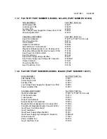
7.3.5 FACTORY PART NUMBERS, MODEL 315-ASX (PART NUMBER 143145)
SUB-ASSEMBLY
FACTORY PART No.
LED Display PCB:
139071
Low Voltage Power Supply/Fan Speed Cant. PCB:
139074
Control/Logic PCB:
139078
Power Amplifier PCB:
140076
Output Filter PCB:
140075
Input Filter PCB:
140079
CHASSIS COMPONENT
FACTORY PART No.
Input Circuit Breaker:
716070 or 716075 for CE units
Front Panel Handle:
702112
Output Terminal Block:
705077
External Sense Terminal Block:
705076
Input Power Cord Strain Relief:
779009
Input Transformer:
531317
Input Power Supply Bridge Rectifier:
743005
Input Power Supply High Voltage DC Capacitor:
720588-41
Output Relay:
717040
Power Amplifier Fan:
703145
7.3.6 FACTORY PART NUMBERS, MODEL 320-ASX ( PART NUMBER 143149 )
SUB-ASSEMBLY
FACTORY PART No.
LED Display PCB:
139071
Low Voltage Power Supply/Fan Speed Cont. PCB:
139074
Power Factor Correction PCB:
139075
Control/Logic PCB:
139078
Power Amplifier PCB:
140076
Output Filter PCB:
140075
Input Filter PCB:
140079
CHASSIS COMPONENT
FACTORY PART No.
Input Circuit Breaker:
716070 or 716075 for CE units
Front Panel Handle:
702112
Output Terminal Block:
705077
External Sense Terminal Block:
705076
Input Power Cord Strain Relief:
779009
Input Transformer (Tl):
531318
Low Voltage Input Transformer (T2):
531290
Output Relay:
717040
Power Amplifier Fan:
703145
Input Transformer Fan:
703136
Содержание ASX series
Страница 2: ......
Страница 8: ......
Страница 21: ...SECTION 2 SPECIFICATIONS 13 2 1 2 OUTPUT POWER cont FIGURE 2 1 2 A MODEL 115 ASX OUTPUT DERATING CURVES ...
Страница 22: ...SECTION 2 SPECIFICATIONS 14 2 1 2 OUTPUT POWER cont FIGURE 2 1 2 B MODEL 120 ASX OUTPUT DERATING CURVES ...
Страница 23: ...SECTION 2 SPECIFICATIONS 15 2 1 2 OUTPUT POWER cont FIGURE 2 1 2 C MODEL 140 ASX OUTPUT DERATING CURVES ...
Страница 24: ...SECTION 2 SPECIFICATIONS 16 2 1 2 OUTPUT POWER cont FIGURE 2 1 2 D MODEL 160 ASX OUTPUT DERATING CURVES ...
Страница 25: ...SECTION 2 SPECIFICATIONS 17 2 1 2 OUTPUT POWER cont FIGURE 2 1 2 E MODEL 315 ASX OUTPUT DERATING CURVES ...
Страница 26: ...SECTION 2 SPECIFICATIONS 18 2 1 2 OUTPUT POWER cont FIGURE 2 1 2 F MODEL 320 ASX OUTPUT DERATING CURVES ...
Страница 27: ...SECTION 2 SPECIFICATIONS 19 2 1 2 OUTPUT POWER cont FIGURE 2 1 2 G MODEL 345 ASX OUTPUT DERATING CURVES ...
Страница 28: ...SECTION 2 SPECIFICATIONS 20 2 1 2 OUTPUT POWER cont FIGURE 2 1 2 H MODEL 360 ASX OUTPUT DERATING CURVES ...
Страница 29: ...SECTION 2 SPECIFICATIONS 21 2 1 2 OUTPUT POWER cont FIGURE 2 1 2 I MODEL 3120 ASX OUTPUT DERATING CURVES ...
Страница 69: ...SECTION 3 INSTALLATION 61 3 4 2 SPLIT PHASE OUTPUT cont FIGURE 3 4 2 1 SPLIT PHASE OUTPUT CONNECTION ...
Страница 70: ...SECTION 3 INSTALLATION 62 3 4 2 SPLIT PHASE OUTPUT cont FIGURE 3 4 2 2 SPLIT PHASE OUTPUT CONNECTION ...
Страница 72: ...SECTION 3 INSTALLATION 64 3 4 3 THREE PHASE OUTPUT cont FIGURE 3 4 3 1 THREE PHASE OUTPUT CONNECTION ...
Страница 73: ...SECTION 3 INSTALLATION 65 3 4 3 THREE PHASE OUTPUT cont FIGURE 3 4 3 2 THREE PHASE OUTPUT CONNECTION ...
Страница 76: ...SECTION 3 INSTALLATION 68 3 5 CONNECTION OF SYSTEM CONTROL UNIT SCU cont FIGURE 3 5 1 SCU CONNECTION ...


