


SECTION 3 INSTALLATION
43
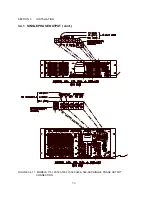
3.2.5 OUTPUT VOLTAGE RANGE CONFIGURATION, MODEL 3120-ASX
This paragraph describes the configuration of the Output Voltage Range for the Model 3120-ASX
Power Source. This model can be configured for either 0-135 VAC
l-n
, 0-203 VAC
l-n
, 0-270 VAC
l-n
,
or 0-338 VAC
l-n
. The 0-203 VAC range is designated as the VR1.5 output form. The 0-270 VAC
range is defined to be the VR2.0 output form and, finally, the 0-338 VAC range is defined to be the
VR2.5 output form. A Magnetics Module (Assembly No. 140700) is required for the 203, 270, and
338 VAC output forms.
Refer to Figure 3.2.5 for location of components referenced below and range tap selection
information.
Conversion to the 203 VAC Output Range (VR1.5) is as follows:
1)
Remove the top cover of the Magnetics Module.
2)
Wire for 1.5:1 ratio as per wire table of Figure 3.2.5.
3)
Replace top cover of Magnetics Module.
4)
Connect Magnetics Module to the power source. The Magnetics Module is connected to
the power source by attaching P20A and P20B of the Magnetics Module to J20A and
J20B, respectively, of the power source. Also be sure to connect the Chassis GND wire
of the Magnetics Module to the CHS GND stud on the rear panel of the power source.
5)
Set the Transformer Ratio Setting of the UPC-3 to 1.5. (Refer to the UPC-Series
Operation Manual for details.) The Transformer Ratio Setting is set to 0.0 on systems not
equipped with output transformers.
6)
Set the Amps to Volts Ratio Setting of the UPC-3 to 60. (Refer to the UPC-Series
Operation Manual for details.)
7)
Calibrate the power source as stated in Section 6 of this manual.
Conversion to the 270 VAC Output Range (VR2.0) proceeds as above, except that the Magnetics
Module is wired for the 2.0:1 ratio and the Transformer Ratio Setting of the UPC-3 is set for 2.0.
Likewise, conversion to the 338 VAC Output Range (VR2.5) proceeds as above, except that the
Magnetics Module is wired for the 2.5:1 ratio and the Transformer Ratio Setting of the UPC-3 is set
for 2.5.
The Transformer Ratio Setting of the UPC-3 is set to 0.0 on systems without transformer-coupled
outputs.
While the above procedure can be performed in the field, Pacific Power Source recommends that
the system be returned to the factory when transformer-coupled outputs are to be added to the
system. This insures proper connection and calibration of the entire system.
Содержание ASX series
Страница 2: ......
Страница 8: ......
Страница 21: ...SECTION 2 SPECIFICATIONS 13 2 1 2 OUTPUT POWER cont FIGURE 2 1 2 A MODEL 115 ASX OUTPUT DERATING CURVES ...
Страница 22: ...SECTION 2 SPECIFICATIONS 14 2 1 2 OUTPUT POWER cont FIGURE 2 1 2 B MODEL 120 ASX OUTPUT DERATING CURVES ...
Страница 23: ...SECTION 2 SPECIFICATIONS 15 2 1 2 OUTPUT POWER cont FIGURE 2 1 2 C MODEL 140 ASX OUTPUT DERATING CURVES ...
Страница 24: ...SECTION 2 SPECIFICATIONS 16 2 1 2 OUTPUT POWER cont FIGURE 2 1 2 D MODEL 160 ASX OUTPUT DERATING CURVES ...
Страница 25: ...SECTION 2 SPECIFICATIONS 17 2 1 2 OUTPUT POWER cont FIGURE 2 1 2 E MODEL 315 ASX OUTPUT DERATING CURVES ...
Страница 26: ...SECTION 2 SPECIFICATIONS 18 2 1 2 OUTPUT POWER cont FIGURE 2 1 2 F MODEL 320 ASX OUTPUT DERATING CURVES ...
Страница 27: ...SECTION 2 SPECIFICATIONS 19 2 1 2 OUTPUT POWER cont FIGURE 2 1 2 G MODEL 345 ASX OUTPUT DERATING CURVES ...
Страница 28: ...SECTION 2 SPECIFICATIONS 20 2 1 2 OUTPUT POWER cont FIGURE 2 1 2 H MODEL 360 ASX OUTPUT DERATING CURVES ...
Страница 29: ...SECTION 2 SPECIFICATIONS 21 2 1 2 OUTPUT POWER cont FIGURE 2 1 2 I MODEL 3120 ASX OUTPUT DERATING CURVES ...
Страница 69: ...SECTION 3 INSTALLATION 61 3 4 2 SPLIT PHASE OUTPUT cont FIGURE 3 4 2 1 SPLIT PHASE OUTPUT CONNECTION ...
Страница 70: ...SECTION 3 INSTALLATION 62 3 4 2 SPLIT PHASE OUTPUT cont FIGURE 3 4 2 2 SPLIT PHASE OUTPUT CONNECTION ...
Страница 72: ...SECTION 3 INSTALLATION 64 3 4 3 THREE PHASE OUTPUT cont FIGURE 3 4 3 1 THREE PHASE OUTPUT CONNECTION ...
Страница 73: ...SECTION 3 INSTALLATION 65 3 4 3 THREE PHASE OUTPUT cont FIGURE 3 4 3 2 THREE PHASE OUTPUT CONNECTION ...
Страница 76: ...SECTION 3 INSTALLATION 68 3 5 CONNECTION OF SYSTEM CONTROL UNIT SCU cont FIGURE 3 5 1 SCU CONNECTION ...


