


SECTION 3 INSTALLATION
67
3.5
CONNECTION OF SYSTEM CONTROL UNIT (SCU)
This paragraph describes the connection of the System Control Unit (SCU) to an ASX-Series
Power Source.
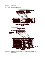
Figure 3.5.1 shows the SCU connected to the Model 360-ASX Power Source. (Other models are
connected similarly.) In this configuration, the controller is removed from the power source chassis
and replaced with patch cables which route signals to the rear panel. Two shielded 30-conductor
(15 twisted pairs) cable assemblies are used to connect the SCU to the power source. The cables
are wired one-to-one and outfitted with DB-25P connectors on both ends. Hence, they cannot be
installed backwards. This interface is designed to operate with cable lengths up to 50 feet.
Cables, ten feet in length, are stocked by Pacific Power Source as P/N 134121. Contact Customer
Service for cables of lengths other than ten feet. Refer to the UPC-Series Operation Manual for
details regarding the SCU.
Note that in this configuration, Remote Interface ( GPIB or RS-232) and AUX I/O connections are
made at the SCU.
UPC
INSTALLATION
The ASX-Series controller is modular in nature. This is a design feature which allows the user to
tailor the control characteristics of the system. While it is possible to change controllers in the field,
Pacific Power Source (PPS) recommends that the unit be returned to the factory when controller
exchange is desired. This insures proper installation and calibration of the system by PPS
technicians.
The installation of the UPC is described in the UPC-Series Operation Manual. The procedure is
stated for installation into the System Control Unit (SCU). Installation of the UPC into the power
source chassis proceeds in a similar manner. The primary difference between the various units is
the routing of the ribbon cables to the rear panel. Be sure to note the routing of these cables before
removing the existing controller; install the ribbon cables of the new UPC using the same routing.
After the new UPC is in place and connected, calibration is required. Refer to Section 6 of this
manual.
Содержание ASX series
Страница 2: ......
Страница 8: ......
Страница 21: ...SECTION 2 SPECIFICATIONS 13 2 1 2 OUTPUT POWER cont FIGURE 2 1 2 A MODEL 115 ASX OUTPUT DERATING CURVES ...
Страница 22: ...SECTION 2 SPECIFICATIONS 14 2 1 2 OUTPUT POWER cont FIGURE 2 1 2 B MODEL 120 ASX OUTPUT DERATING CURVES ...
Страница 23: ...SECTION 2 SPECIFICATIONS 15 2 1 2 OUTPUT POWER cont FIGURE 2 1 2 C MODEL 140 ASX OUTPUT DERATING CURVES ...
Страница 24: ...SECTION 2 SPECIFICATIONS 16 2 1 2 OUTPUT POWER cont FIGURE 2 1 2 D MODEL 160 ASX OUTPUT DERATING CURVES ...
Страница 25: ...SECTION 2 SPECIFICATIONS 17 2 1 2 OUTPUT POWER cont FIGURE 2 1 2 E MODEL 315 ASX OUTPUT DERATING CURVES ...
Страница 26: ...SECTION 2 SPECIFICATIONS 18 2 1 2 OUTPUT POWER cont FIGURE 2 1 2 F MODEL 320 ASX OUTPUT DERATING CURVES ...
Страница 27: ...SECTION 2 SPECIFICATIONS 19 2 1 2 OUTPUT POWER cont FIGURE 2 1 2 G MODEL 345 ASX OUTPUT DERATING CURVES ...
Страница 28: ...SECTION 2 SPECIFICATIONS 20 2 1 2 OUTPUT POWER cont FIGURE 2 1 2 H MODEL 360 ASX OUTPUT DERATING CURVES ...
Страница 29: ...SECTION 2 SPECIFICATIONS 21 2 1 2 OUTPUT POWER cont FIGURE 2 1 2 I MODEL 3120 ASX OUTPUT DERATING CURVES ...
Страница 69: ...SECTION 3 INSTALLATION 61 3 4 2 SPLIT PHASE OUTPUT cont FIGURE 3 4 2 1 SPLIT PHASE OUTPUT CONNECTION ...
Страница 70: ...SECTION 3 INSTALLATION 62 3 4 2 SPLIT PHASE OUTPUT cont FIGURE 3 4 2 2 SPLIT PHASE OUTPUT CONNECTION ...
Страница 72: ...SECTION 3 INSTALLATION 64 3 4 3 THREE PHASE OUTPUT cont FIGURE 3 4 3 1 THREE PHASE OUTPUT CONNECTION ...
Страница 73: ...SECTION 3 INSTALLATION 65 3 4 3 THREE PHASE OUTPUT cont FIGURE 3 4 3 2 THREE PHASE OUTPUT CONNECTION ...
Страница 76: ...SECTION 3 INSTALLATION 68 3 5 CONNECTION OF SYSTEM CONTROL UNIT SCU cont FIGURE 3 5 1 SCU CONNECTION ...


