


SECTION 3 INSTALLATION
55
3.3.6 INPUT POWER WIRING REQUIREMENTS
The Models 115-ASX, 120-ASX, 140-ASX, 160-ASX, 315-ASX, 320-ASX, 345-ASX, and
360-ASX are supplied with an input power cord. Install an appropriate plug onto the end
of the power cord and connect to the proper outlet. Refer to the table below for the proper
wire color of each connection. The Power Sources with 3 phase input are not sensitive to
phase rotation of the input voltage. Refer to paragraph 2.1.1 for recommended input
service of the configured input voltage form.
Wire Color
( US Models )
Wire Color
( European Models )
1
φ
LINE ( HI )
Black
Brown
NEUTRAL ( LO )
White
Blue
GROUND ( CHS )
Green
Green-Yellow
3
φ
LINE 1 ( L1 )
Black
Brown
LINE 2 ( L2 )
Orange
Black
LINE 3 ( L3 )
Red
Grey
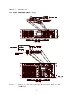
The input power of the Model 3120-ASX connects to the Input Power terminal block located
on the rear panel of the power source. The connection points are labeled "A," "B," "C," "N,"
and "CHS". The input wiring is connected to these points in the appropriate order with CHS
being the safety ground or earth potential. The 3120-ASX Power Source is not sensitive to
phase rotation of the input voltage. For all standard DELTA input voltage forms (208, 220,
and 240 VAC) the “N” terminal is not used. For WYE input voltage forms (220/380, 240/416
and 277/480 VAC), the "N" terminal connection is optional. Refer to Figure 3.3.9 for the
proper wire size to be used with the configured input power form.
CAUTION
CONNECTION OF THIS UNIT TO IMPROPER INPUT VOLTAGES WILL CAUSE
CATASTROPHIC DAMAGE TO THE POWER SOURCE.
READ THE INPUT VOLTAGE LABEL AND CONNECT TO THAT INPUT VOLTAGE ONLY. IF
THERE ARE ANY QUESTIONS, CONTACT THE FACTORY.
NOTE: It is the user's responsibility to meet all local and national electrical codes when
installing this equipment.
WARNING
LETHAL VOLTAGE PRESENT AT INPUT TERMINALS OF THIS MACHINE.
ALWAYS CONNECT "CHS or GND" TERMINAL TO EARTH POTENTIAL.
FAILURE TO DO SO WILL CREATE A SHOCK HAZARD.
Содержание ASX series
Страница 2: ......
Страница 8: ......
Страница 21: ...SECTION 2 SPECIFICATIONS 13 2 1 2 OUTPUT POWER cont FIGURE 2 1 2 A MODEL 115 ASX OUTPUT DERATING CURVES ...
Страница 22: ...SECTION 2 SPECIFICATIONS 14 2 1 2 OUTPUT POWER cont FIGURE 2 1 2 B MODEL 120 ASX OUTPUT DERATING CURVES ...
Страница 23: ...SECTION 2 SPECIFICATIONS 15 2 1 2 OUTPUT POWER cont FIGURE 2 1 2 C MODEL 140 ASX OUTPUT DERATING CURVES ...
Страница 24: ...SECTION 2 SPECIFICATIONS 16 2 1 2 OUTPUT POWER cont FIGURE 2 1 2 D MODEL 160 ASX OUTPUT DERATING CURVES ...
Страница 25: ...SECTION 2 SPECIFICATIONS 17 2 1 2 OUTPUT POWER cont FIGURE 2 1 2 E MODEL 315 ASX OUTPUT DERATING CURVES ...
Страница 26: ...SECTION 2 SPECIFICATIONS 18 2 1 2 OUTPUT POWER cont FIGURE 2 1 2 F MODEL 320 ASX OUTPUT DERATING CURVES ...
Страница 27: ...SECTION 2 SPECIFICATIONS 19 2 1 2 OUTPUT POWER cont FIGURE 2 1 2 G MODEL 345 ASX OUTPUT DERATING CURVES ...
Страница 28: ...SECTION 2 SPECIFICATIONS 20 2 1 2 OUTPUT POWER cont FIGURE 2 1 2 H MODEL 360 ASX OUTPUT DERATING CURVES ...
Страница 29: ...SECTION 2 SPECIFICATIONS 21 2 1 2 OUTPUT POWER cont FIGURE 2 1 2 I MODEL 3120 ASX OUTPUT DERATING CURVES ...
Страница 69: ...SECTION 3 INSTALLATION 61 3 4 2 SPLIT PHASE OUTPUT cont FIGURE 3 4 2 1 SPLIT PHASE OUTPUT CONNECTION ...
Страница 70: ...SECTION 3 INSTALLATION 62 3 4 2 SPLIT PHASE OUTPUT cont FIGURE 3 4 2 2 SPLIT PHASE OUTPUT CONNECTION ...
Страница 72: ...SECTION 3 INSTALLATION 64 3 4 3 THREE PHASE OUTPUT cont FIGURE 3 4 3 1 THREE PHASE OUTPUT CONNECTION ...
Страница 73: ...SECTION 3 INSTALLATION 65 3 4 3 THREE PHASE OUTPUT cont FIGURE 3 4 3 2 THREE PHASE OUTPUT CONNECTION ...
Страница 76: ...SECTION 3 INSTALLATION 68 3 5 CONNECTION OF SYSTEM CONTROL UNIT SCU cont FIGURE 3 5 1 SCU CONNECTION ...