


SECTION 3 INSTALLATION
69
3.6 REMOTE
INTERFACE
The UPC-Series programmable controller is supplied with one of two remote interfaces. These are
the GPIB (General Purpose Interface Bus) or RS-232 Interface. Connection information relative to
these interfaces is described in detail in the UPC-Series Operation manual.
On systems outfitted with the SCU, all remote interface connections and configuration settings are
made at the SCU.
3.7
AUX I/O INSTALLATION
This paragraph describes connection of the AUXiliary Input/Output signals. These signals vary
between the different controllers. However the method of connection remains the same.
The AUX I/O connector contains synchronizing outputs (digital) and modulation inputs (analog).
These are extremely useful in certain test applications, particularly, single event phenomena.
Modulation inputs are also present on this connector. The use of any of these signals is optional
and connection to these points is required only when these features are used.
The AUX I/O connector is located on the rear panel of the power source (or SCU, when present)
and is labeled as such. This is a DB-25S connector. A DB-25P connector is required for
connection to AUX I/O connector.
On systems outfitted with the SCU, the AUX I/O connections are made at the SCU.
All signals contained within the AUX I/O connector are low-level (less than ±15 VDC) and are with
respect to earth ground reference. Refer to the appropriate controller operation manual for
complete definition of the signals present on the AUX I/O connector.
Содержание ASX series
Страница 2: ......
Страница 8: ......
Страница 21: ...SECTION 2 SPECIFICATIONS 13 2 1 2 OUTPUT POWER cont FIGURE 2 1 2 A MODEL 115 ASX OUTPUT DERATING CURVES ...
Страница 22: ...SECTION 2 SPECIFICATIONS 14 2 1 2 OUTPUT POWER cont FIGURE 2 1 2 B MODEL 120 ASX OUTPUT DERATING CURVES ...
Страница 23: ...SECTION 2 SPECIFICATIONS 15 2 1 2 OUTPUT POWER cont FIGURE 2 1 2 C MODEL 140 ASX OUTPUT DERATING CURVES ...
Страница 24: ...SECTION 2 SPECIFICATIONS 16 2 1 2 OUTPUT POWER cont FIGURE 2 1 2 D MODEL 160 ASX OUTPUT DERATING CURVES ...
Страница 25: ...SECTION 2 SPECIFICATIONS 17 2 1 2 OUTPUT POWER cont FIGURE 2 1 2 E MODEL 315 ASX OUTPUT DERATING CURVES ...
Страница 26: ...SECTION 2 SPECIFICATIONS 18 2 1 2 OUTPUT POWER cont FIGURE 2 1 2 F MODEL 320 ASX OUTPUT DERATING CURVES ...
Страница 27: ...SECTION 2 SPECIFICATIONS 19 2 1 2 OUTPUT POWER cont FIGURE 2 1 2 G MODEL 345 ASX OUTPUT DERATING CURVES ...
Страница 28: ...SECTION 2 SPECIFICATIONS 20 2 1 2 OUTPUT POWER cont FIGURE 2 1 2 H MODEL 360 ASX OUTPUT DERATING CURVES ...
Страница 29: ...SECTION 2 SPECIFICATIONS 21 2 1 2 OUTPUT POWER cont FIGURE 2 1 2 I MODEL 3120 ASX OUTPUT DERATING CURVES ...
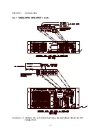
Страница 69: ...SECTION 3 INSTALLATION 61 3 4 2 SPLIT PHASE OUTPUT cont FIGURE 3 4 2 1 SPLIT PHASE OUTPUT CONNECTION ...
Страница 70: ...SECTION 3 INSTALLATION 62 3 4 2 SPLIT PHASE OUTPUT cont FIGURE 3 4 2 2 SPLIT PHASE OUTPUT CONNECTION ...
Страница 72: ...SECTION 3 INSTALLATION 64 3 4 3 THREE PHASE OUTPUT cont FIGURE 3 4 3 1 THREE PHASE OUTPUT CONNECTION ...
Страница 73: ...SECTION 3 INSTALLATION 65 3 4 3 THREE PHASE OUTPUT cont FIGURE 3 4 3 2 THREE PHASE OUTPUT CONNECTION ...
Страница 76: ...SECTION 3 INSTALLATION 68 3 5 CONNECTION OF SYSTEM CONTROL UNIT SCU cont FIGURE 3 5 1 SCU CONNECTION ...


