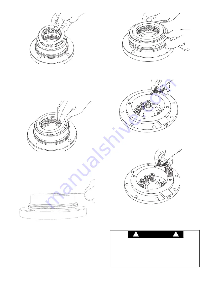
3. Insert first, a steel brake disc against the spacer fol-
lowed by a friction brake disc then alternate steel and
friction discs until seven (7) friction and eight (8) steel
discs have been installed. Finish with a steel brake
disc on top.
NOTE:
It is a good practice to pre-lubricate the discs
in light motor oil prior to assembly.
4. Install the remaining brake spacer on top of the last
steel brake disc. (This is the only spacer used with
lobed discs, except on some of the 67:1 ratio units
with the 1.3 displacement motors, two of the spacers
are stacked on the brake discs.)
5. To check brake stack height, apply light pressure to
the brake spacer. Hold brake spacer down firmly by
hand and measure clearance in three places between
uppermost motor support flange and brake spacer.
Brake spacer must rise above uppermost flange .080
in. (2 mm) maximum and .000 in (.00 mm). If the gap
exceeds the maximum limit, there are too many brake
discs in stack-up or the discs are distorted. If the gap
is less than the minimum, there are too few discs in
stack-up or the discs are worn out.
6. Lubricate the brake piston seal and motor support
sealing surface with petroleum jelly or hydraulic oil.
Install new piston seal to motor support, seal lip down.
OLDER STYLE BRAKE CYLINDER
7. Install brake springs into brake cylinder
NEW STYLE BRAKE CYLINDER
7A.When using the new style brake cylinder without
milled spring pockets, install the spring spacer, then
the brake springs.
20
Always use the molded spring spacer with the new
brake cylinder. The brake springs must be properly posi-
tioned by the spring spacer. Failure to install the spring
spacer may allow the springs to contact each other and
become damaged. This could result in loss of load con-
trol, property damage, injury or death.
CAUTION
WARNING
!
!
Содержание BRADEN Gearmatic BG6A
Страница 2: ......


