background image


MITSUBISHI HOIST 

Type UM (5t , 10t) 

INSTRUCTION MANUAL 


 Be sure to hand this instruction manual to the person in charge of facilities before starting 

operation. 

  Be sure to have the person in charge of facilities and operators read this manual thoroughly before 

starting operation. 


Instruction Manual PHN14A003

A

Standard Version

Содержание UM 10t

Страница 1: ...o hand this instruction manual to the person in charge of facilities before starting operation Be sure to have the person in charge of facilities and operators read this manual thoroughly before starting operation Instruction Manual PHN14A003 A Standard Version ...

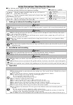
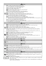
Страница 2: ... the crane Install the crane only in an environment of the specified conditions Avoid rain or water that the crane is not designed for Be sure to ground the crane In addition to the grounding provide the electrical circuit with a ground fault circuit breaker 3 Operation Danger Check that the brake device operates normally before starting to use Do not operate the crane if the brake device does not...

Страница 3: ...abels affixed to the main body Do not operate the crane with the warning or caution labels left illegible Before releasing the operation box from your hand put it back to the naturally suspended position Do not have the operation box hit a person or a thing Before operating the crane check that the lower part of the hook rotates smoothly and freely Be sure to engage the sling ropes and sling devic...

Страница 4: ...ctions and Indication on Segment Indicator 16 Error Detection Function 22 Maintenance and Inspection of Brake 23 Electromagnetic Hoisting Brake 23 Traversing Electromagnetic Brake 26 Inspection and Maintenance of Wire Rope 27 Structure Disassembly and Re assembly of Reduction Gears 28 Hoisting Unit Main reducer 28 Hoisting Unit Sub reducer 29 Traversing Unit 30 Maintenance and Inspection 31 Daily ...

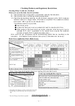
Страница 5: ... or more and less than 12 500 hrs 12 500 hrs or more and less than 25 000 hrs 25 000 hrs or more Hoist crane usually handling less than 50 of rated load A A A B C D E Hoist crane usually handling 50 or more and less than 63 of rated load A A B C D E F Hoist crane usually handling 63 or more and less than 80 of rated load A B C D E F F Hoist crane usually handling 80 or more of rated load B C D E F...

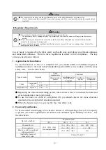
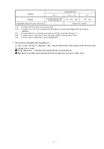
Страница 6: ... a simplified lift you should submit an installation report or installation notice to the local Labor Standards Inspection Office in accordance with the crane safety code See the table below Type of crane Capacity Crane manufacturer Crane user Manufacturing permit Installation notice and performance inspection Installation report Maintenance obligation Crane Suspended load 3 t 1 2 t 3 t Simplified...

Страница 7: ... Jb Personnel who receive training in accordance with the Vocational Training Act Sk Personnel who complete the course of operating skill for floor operated cranes Sl Personnel who complete the course of slinging skill 3 Maintenance Obligation by Regulations To use a hoist the user is obliged to carry out periodical self elected inspections and to retain the inspection records Daily inspection Mon...

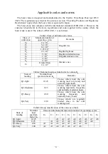
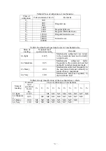
Страница 8: ...termittent use U6 1 106 Irregular intensive use U7 2 106 Intensive use U8 4 106 U9 Greater than 1 6 104 Table2 Nominal load spectrum factor for cranes Kp State of loading Nominal load spectrum factor Kp Remarks Q1 light 0 125 Cranes which hoist the safe working load very rarely and normally light loads Q2 Moderate 0 25 Cranes which hoist the safe working load fairly frequently and normally moderat...

Страница 9: ...imum load and normally to light loads L2 Moderate 0 25 Mechanisms subjected fairly frequently to the maximum load but normally to rather moderate loads L3 Heavy 0 50 Mechanisms subjected frequently to the maximum load and normally to loads of heavy magnitude L4 Very 1 00 Mechanisms subjected regularly to the maximum load Table6 Group classification of the mechanism as a whole State of loading Nomi...

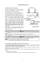
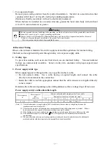
Страница 10: ... that only a specialized subcontractor or persons with the expert knowledge is allowed to install the crane Or else electric shock falling hook block and other accident may occur causing an injury Install the crane only in an environment of the specified conditions Avoid rain or water that the crane is not designed for Warning Be sure to provide both ends of the rails of the cross and longitudinal...

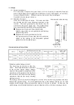
Страница 11: ... and specifications 2 Power supply cable type When supplying power through cable use a specified cabtyre cable Do not connect cables Use a cable having a required length and connect the cable directly to the terminal in the control box Retain the cable in such an appropriate manner that the cable tension is not applied directly to the terminal Determine the cable size depending on the cabling dist...

Страница 12: ... type Characteristics of Noise Filter Model Applicable hoist Outside dimensions Unit mm Approximate weight kg Loss W Leakage current Ref value mA W H D W1 H1 C 200 V SF1259 U2 1 2 2 142 410 65 105 386 6 2 4 27 33 SF1260 U2 2 8 5 222 468 80 190 449 7 5 118 440 Measures against leakage current This hoist uses an inverter to drive the motor Since high harmonics is included in the inverter output volt...

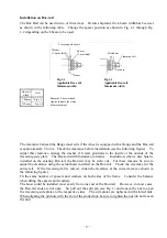
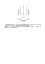
Страница 13: ...the clearance using the actual hoist installed on the Box rail Check the clearance for the entire rail If the traversing rail is curved widen the clearance at the curved area as shown in the following figure Fit the same number of spacers and washers on both sides of the frame Consider the balance when fitting the spacers and washers The hoist could be installed most easily from one end of the Box...

Страница 14: ...ter that eliminate the gap between the clamping bolt and the frame bolt hole and then tighten the nut again If there is a gap between the clamping bolt and the frame bolt hole the wheel may be lifted or the hoist main body may be inclined Wheel Box Rail With flange ...

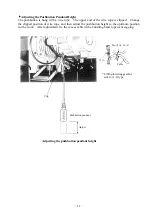
Страница 15: ...e the clipped position of wire rope and then adjust the pushbutton height to the optimum position for the work After adjustment fix the excess cable with a bundling band to prevent sagging Pushbutton pendant Adjust Clip Lifting lowering gearbox side for 1 2t type Clip Cable Adjusting the pushbutton pendant height Banding band Clip ...

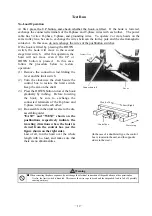
Страница 16: ... the control box to restore the limit switch Keep the arm on the shaft 3 Press the DOWN button to lower the hook gradually by inching Before lowering the hook be sure to exchange the connected terminals of the R phase and T phase wires with each other 4 Re assemble in the order reverse to the dis assembling order EAST and WEST shown on the pushbuttons respectively indicate the traveling directions...

Страница 17: ...allation of I beam and other devices can be checked by this test The test is designed to check the mechanical strength of each part The performance test shall be carried out with the rated load C Adjusting the traversing brake If the brake is too effective when traversing is stopped load collapse may occur On the contrary if the brake is not effective the hoist may coast and cause an accident Open...

Страница 18: ...is function whenever necessary To set the high speed or low speed use the operation function setting area equipped for the standard type The mode button is in this area Using this button enter the frequency setting mode and change the frequency to set the desired speed Speed change between high speed and low speed lifting lowering operation Pressing Pushbutton No load high speed function 1st step ...

Страница 19: ...s an error data OUT2 Outputs the status data hook at lower limit position This data can be also used as an error data Upper limit stop point OUT1 Opened OUT2 Closed Lower limit stop point OUT1 Closed OUT2 Closed Set lift OUT1 Closed OUT2 Opened At abnormal stoppage OUT1 Closed OUT2 Opened Contact capacity 200 VAC 0 5 A Terminal box 20P OUT3 and OUT4 terminals The overload signal will be output eve...

Страница 20: ...or will enter the basic setting mode Press and hold down the button for 2 seconds or more to switch the segment indicator mode Note that the segment indicator mode will be sequentially switched to the extended setting mode history display mode and basic setting mode Each mode has various setting items or display items So switch the segment indicator to the desired mode to change the set operation ...

Страница 21: ...per limit stop point 10 mm below the LS lever Adjusted to any point in the range of lift Fin adjustment setting range 1 to 9999 The limit switches can be respectively turned on and off Butch adjustment of all points is possible Upper limit speed reduction point 150 mm below the upper limit stop point Lower limit speed reduction point 150 mm above the lower limit stop point Lower limit stop point P...

Страница 22: ... frequency by 1 Hz Press the S and S buttons at the same time to store the current position Press the button to lift the set position by 1 mm will flash Press the button to enable the No load high speed function for the selected operation type will light Press the button to raise the overload judgment level by 1 For low speed For high speed Press the button to reduce the frequency by 1 Hz Press th...

Страница 23: ...lue therefore does not represent a physical quantity of the load The optimum overload judgment level depends on the model If the overload judgment level is raised the overload stoppage function will not be easily activated a heavier load can be lifted because the overload stoppage function is not easily activated If the power supply voltage is low overload may be detected even if the applied load ...

Страница 24: ...ment indicator 4 Follow the procedure shown below to activate the overload stoppage function at the load of 2t for the hoist of 2 8t class to lower the overload judgment level Power on Press this button several times Low speed lifting operation Press this button several times to display oL L on the segment indicator Reduce the judgment value Press this button several times to display oL on the seg...

Страница 25: ...nd lowering operations The operation time can be displayed in the range of 0 hour and 0 minute to 999 999 hours and 59 minutes The displayed operation time is the total operation time of both the lifting and lowering operations Example of operation in history display mode 1 If you want to know the number of starting times and the operation time stored at detection of the latest error follow the pr...

Страница 26: ... 760 V or more Immediate stoppage Error indication Overloaded during lowering operation Defective regenerative circuit Possible Er13 Lowered during lifting operation During lifting operation or stoppage of operation the hook is lowered Immediate stoppage Error indication Defective hoisting brake Defective inverter Possible Er14 Overwork Overcurrent Control power supply error The Fout signal is out...

Страница 27: ...ving the bolts In this way you can prevent the lid from springing out 2 Using the bolts removed from the lid temporarily tighten the movable iron core and the pressure plate CAUTION If the movable iron core and the pressure plate are not temporarily tightened the adjusting ring may fall off or two retaining springs small springs that ensure easy falling down of the adjusting ring may be missing 3 ...

Страница 28: ...ve the brake gear Use two threaded holes size M8 for removal of the brake gear Before reassembly be sure to fill the inner groove with Moly PS grease No 2 6 After inserting the retaining springs fit the adjusting ring into the deeper side upper side of the eccentric groove of the pressure plate After that attach the movable iron core to the adjusting ring and then tighten the movable iron core usi...

Страница 29: ...the center of the stationary core The gap should be in the range of 0 1 mm to 0 3 mm normally 3 Check that the edges of the shoulders of the pressure plate and the adjusting ring are chamfered properly Normally the chamfer should be C0 2 or less refer to the following figure 4 If the brake gear has been disassembled apply grease to the inner circumference 5 Do not forget to fit the packing between...

Страница 30: ...d 50 of the motor torque To change the braking force according to loading conditions adjust the brake torque in the following procedure Remove the brake cover and you can see the adjusting bolt hexagon head bolt in the center To increase the brake torque turn clockwise the adjusting bolt To decrease turn counterclockwise The adjustment range is 0 to 100 of the motor torque In the monthly inspectio...

Страница 31: ...t for strength This hoist crane Type M uses the Mitsubishi original high strength wire rope Be sure to use the Mitsubishi genuine wire rope for replacement The genuine wire rope has a stamp of the Mitsubishi mark at the end The rope stationary end easily comes off the drum while the wire rope is being replaced Tie the rope with a string as a measure to prevent the wire rope from falling when the r...

Страница 32: ...part is distorted or chipped replace it with a new one 4 To reassemble the unit follow the above disassembly procedure in the reversed order Apply grease to the gears first and then tighten the G cover Before tightening the G cover completely degrease the mating faces of the G cover and the frame and apply the liquid packing Three Bond No 1208D or No 1104 to both mating faces Lubrication when reas...

Страница 33: ... reversed order First stuff the gear box with grease Then tighten the L bracket Before tightening the L bracket completely degrease the mating faces of the Gear box and the L bracket and apply the liquid packing Three Bond No 1208D or No 1104 to both mating faces Lubrication when reassembling the disassembled unit Stuff the clearance between the wall of the sub reduction gear unit box and the gear...

Страница 34: ...quantity for each type During reassembly apply liquid packing Pos seal manufactured by CEMEDINE Co Ltd or Three Bond No 1208D to the mating faces between the traversing side plate and the G case Grease quantity Capacity t 5t Model Mono rail Double rail Place In a gear box Exposure gear In a gear box Grease quantity g Application to entire gear surface 300 Recommended grease Moly PS Grease No 2 Man...

Страница 35: ...at the hoist is defective 4 Check for strange noise odor and vibration 5 Check whether the brake is effective For Type UR check whether the immediate stoppage is possible during high speed lifting operation 6 Check that the hoist smoothly moves as directed by the pushbuttons Check that the hoist moves correctly at low and high speeds Check that the speed can be switched smoothly between low and hi...

Страница 36: ...ct or repair the crane Make sure that the crane is free of a load before starting maintenance inspection or repair If maintenance or inspection reveals a defect with the crane do not use the crane until the defects is repaired and rectified Never use the crane with a defect as it is dangerous Or else an accident may occur Caution Before starting maintenance inspection or repair be sure to post or ...

Страница 37: ...s return to position smoothly 5 Check the operation of the overwinding limit switch lever If the pin has been dropped the switch lever will not function Check that the lever functions cor rectly Check that the lever has been properly adjusted 6 Wire rope Check the strands for breakage Less than 10 of number of strands in one twisted wire Check for wear 7 or less of the nominal diameter Check for k...

Страница 38: ...tion sensor Remove the cover and then visually check the RRS board for dust and corrosion and the rotational shaft for distortion 13 Inverter Check the installation condition of the inverter Also check the appearance of the inverter Check the inverter tightening screws for looseness 14 Control box Check the inside of the control box for dust Check the printed boards particularly carefully Check th...

Страница 39: ...heck the overwinding limit switch and contacts for wear Check the clamping screws for looseness Check that the switch and the contacts are tightened properly Check that the switch and the contacts operate properly 8 Check the trolley wire for looseness and rust Check the wires 9 Check the current collector for contact failure and wear Check the rotation Check the wire connections for looseness Che...

Страница 40: ...hickness check check the engagement between the brake disk teeth and the motor shaft or the brake gear for abnormalities wear and backlash 4 DC electromagnet Every year Every 6 months if the frequency of uses is high Remove the stationary core and disassemble the parts After that check the movable parts for wear and backlash At the completion of check lubricate each part Check operation of the aut...

Страница 41: ...ar box Refer to the traversing unit described in Structure Disassembly and Reassembly of Reduction Gears To be applied to the gear surface Once per year Each individual ball bearing section Lithium series grease No 2 or equivalent Multi purpose grease Refill lubrication oil up to around 1 3 of the entire space At overhaul Both sides sealed up ball bearing The external part only shall be cleaned wh...

Страница 42: ...ke cores When there is no clearance between the center legs of the movable and stationary cores which have been fitted to each other New core Approx 0 3 mm Brake mechanism Abnormal operation Current collector wheel When the center diameter reaches 35 mm New wheel 45 mm in diameter Traversing wheel tread Wear of 5 of the original size Difference between left and right wheel diameters of 1 Fig 5 Cab...

Страница 43: ...described on the right side should be observed 3 Hoist or pushbutton pendant insulation failure 3 Check and repair 4 Current leaking from other equipment or wiring reaches the hoist through the I beam 4 Check and repair 5 The floor conductivity is high The floor is wet with a highly conductive liquid such as water The hoist is on a highly conductive surface such as an iron plate steel structure an...

Страница 44: ... the hoist stops 6 Use the hoist at appropriate intervals 8 The hoist lowers and stops during hoisting 1 Overload 1 Reduce the load 2 Hoisting motor overheat 2 Use the hoist at appropriate intervals 3 Hoisting motor wire breakage 3 Check and repair 9 The hoist stops suddenly during hoisting 1 Inverter trip due to overvoltage caused by hoisting an overload 1 Reduce the load 2 Inverter overvoltage t...

Страница 45: ...e relay does not function properly 2 Replace the relay 3 The electromagnetic contactor cannot properly cut off the power 3 Check the internal wiring 4 Adhesion of oil to the brake disk 4 Degrease the brake disk or replace the brake disk 5 The immediate cut off contactor does not operate properly Direct current 17 The traversing brake is too effective or ineffective 1 Brake adjustment failure 1 Adj...

Страница 46: ...The pushbutton will not go down smoothly or will not smoothly pop up 1 Foreign material caught by inner unit 2 Defective inner unit 1 Check or repair 2 Replace 25 Pressing the DOWN pushbutton lowers the load but pressing the UP pushbutton also lowers the load 1 Rotor slippage The rotor is not properly engaged with the motor shaft 1 Replace In this case releasing the pushbutton will immediately sto...

Страница 47: ... 160 V 50 Hz or more Cannot be used if the voltage is below the above value For a detailed description of the corrective method refer to Item 10 described in the previous table If three phases are not balanced the cause of unbalance is cause 1 of Item 10 described in the previous table In this case repair the problem part Note The voltage readings in step 4 above represent the lowest values when t...

Страница 48: ... 44 Developed Connection Diagram of Electric Hoist 5t 10t Lifting Lowering Inverter Hoist Suspended type Frame mounted type ON OFF P1 U P2 D PF60417 ...

Страница 49: ... 45 Developed Connection Diagram of Electric Hoist 5t Electric traversing type ON OFF P1 U P2 D P3 E P4 W P5 S P6 N PF60418 ...

Страница 50: ... 46 Developed Connection Diagram of Electric Hoist 10t Electric traversing type ON OFF P1 U P2 D P3 E P4 W P5 S P6 N PF60419 ...

Страница 51: ... 47 Structural Drawing of Hoist Main Body 5t 10t PA00531 ...

Страница 52: ... 48 Structural Drawing of Electric Traversing Unit Monorail Type 10t P288922 ...

Страница 53: ... 49 Structural Drawing of Electric Traversing Unit Double rail type 5t PA00483 ...

Страница 54: ... 50 Structural Drawing of Traversing Mortor Double rail type 10t P276926 ...

Страница 55: ... 51 Structural Drawing of Hook Block 5t PG49975 ...

Страница 56: ... 52 Structural Drawing of Hook Block 10t PG49976 ...

Страница 57: ...ntanglement When the hook block turns 360 the rope is entangled twice When there are two falls the rope is entangled once The hook block turns 180 4 fall type 2 fall type 4 fall type 2 fall type S twist Z twist 2 Untangle the wire rope until the rope supports wire rope ends can be seen Rope support Rope support 4 fall type 3 Then before removing the rope supports mark the rope supports or rope wit...

Страница 58: ...the hook block on to the ground to sag the wire rope and give several turns number of twists 1 twist to the wire rope turning the wire rope in the direction shown below In the case of the 4 fall type carry out this operation on each side 6 After straightening the wire rope turn the hook 180 clockwise and counterclockwise and make sure that the hook returns to the initial position If there is a non...

Страница 59: ...st is modified altered or operated in a manner that are not admitted by regulations or by the manufacturer 2 Defects caused by the following events 1 Defects due to external factors and causes such as smoke chemicals metal particles or radiated heat 2 Conditions judged as defects by personal feeling which do not affect the normal functions of the hoist Noise vibration inclination of main body etc ...

Страница 60: ...MITSUBISHI ELECTRIC FA INDUSTRIAL PRODUCTS CORPORATION Specifications subject to change without notice ...

Отзывы: