


Operator's Manual
Issue 14
/
Mar 2016 / UMC0071
Mercury
iPS
©2016 Oxford Instruments NanoScience. All rights reserved.
Page
55
LRMZ = Lead Rate, Magnet at Zero
LRMF = Lead Rate, Magnet at Field
MRFa = Magnet Rate – Fast
MRSl = Magnet Rate – Slow
Lead Rate limits are effective when the switch heater is OFF for power supplies that have been
configured with a persistent switch. Under these conditions the power supply is ramping its
output current but not the magnet current. In general the LRMZ and LRMF table entries will be
the same (Figure 15). Only some special case NMR magnets will have different values for
LRMZ and LRMF.
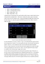
Figure 15. Rate limits table showing example lead rate (LR) entries.
The rate limit table has 4 columns. Column 1, “Type” on the left specifies the type of rate limit
that is being defined. Column 2, “From (A)” specifies the lower current at which the limit will be
applied. Column 3, “To (A)” specifies the upper current at which the limit will be applied.
Column 4, “Rate Limit (A/min)” is the limit value which will be applied to the ramp for all output
current values between the “From” and “To” values. The limit is applied to the group output
(e.g. GRPZ) not the individual power supply device outputs.
The rate limit should be specified for the entire expected operational range of the system, i.e.
from 0A up to the current limit specified in the configuration table (section 4.4). It is possible to
set different limits for different ranges but the ranges must form a continuous set so that the
entire current range has a defined limit, to a range resolution of 0.1mA. If there is a gap in the
limit range a default value of 0.1A/min will be applied and this will cause operational problems.


