


Operator's Manual
Issue 14
/
Mar 2016 / UMC0071
Mercury
iPS
©2016 Oxford Instruments NanoScience. All rights reserved.
Page
100
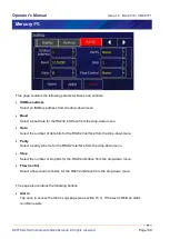
Apply
Tap once to apply (save) changes made on this page.
Home
Tap once to return to the Home page.
9.1.2 Serial RS232 cabling requirements
The RS232 interface is connected via a 25-way D-socket on the rear page. The iPS is
configured as Data Circuit-terminating Equipment (DCE), with the standard pin-assignations
listed in the table below.
Most computer RS232 interfaces are configured as Data Terminal Equipment (DTE). If the
computer has a 25-way D-plug, the cable must be connected pin-to pin (i.e. Pin 1 to Pin 1, Pin 2
to Pin 2 etc.). If the computer has a 9-way D-plug, a standard RS232 9-way to 25-way cable is
required.
Pin
Signal name
Notes
1
FG
Linked to chassis ground inside the iPS.
2
TD
Data from the computer to the iPS.
3
RD
Data from the iPS to the computer.
4
RTS
Linked to Pin 5 inside the iPS.
5
CTS
Linked to Pin 4 inside the iPS.
6
DSR
Linked to +5 V when the iPS is powered.
7
SG
Linked to digital ground inside the iPS.
8
DCD
Linked to +5 V when the iPS is powered.
9 to 25
Open circuit
The iPS does not require signals to be present on the RTS or DTR (pin 20) lines. The RTS
signal is fed back to the computer as CTS. The iPS sends logic high levels (+5 V) to the
computer on DSR and DCD.
Voltage levels for the transmitted and received data are as follows.
Signal
Allowed voltage
Tx data high
>+5.5 V
Tx data low
<-5.5 V
Rx data high threshold
<+2.6 V
Rx data low threshold
>+1.4 V


