


Operator's Manual
Issue 14
/
Mar 2016 / UMC0071
Mercury
iPS
©2016 Oxford Instruments NanoScience. All rights reserved.
Page
46
Figure 11. Schematic circuit for an iPS180-20 showing the 6 current source units.
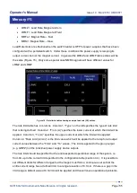
If the “Matrix” configuration has been selected for the Z-axis the Z-axis grouping table will be a
table. The matrix combination will be used for power supplies which require high-current and
high-voltage such as an iPS180-20. The iPS will be configured as parallel sets of series units.
So in the example case of the iPS180-20 this 6 units, 1 x master and 5 x slaves configured as 3
parallel sets of series pairs. So PSU.M1 and PSU.M2 in a 60A, 20V series pair in parallel with
PSU.M3 and PSU.M4 as a 60A, 20V series pair and theses in parallel with PSU.M5 and
PSU.M6 as a 60A, 20V series pair. The 3 pairs in parallel give 180A (see Figure 11).
In this case, to populate the grouping table tap on the top left cell first and select the unit e.g.
PSU.M1 from the drop-down list. Continue to populate the other cells as required remembering
that columns are series combinations and rows are parallel combinations. For the iPS180-20
example shown in Figure 11 the table would look like
PSU.M1
PSU.M3
PSU.M5
PSU.M2
PSU.M4
PSU.M6
Figure 12. Engineering Configuration grouping table for an iPS180-20. PSU.M1 is in series with PSU.M2. PSU.M3 is in
series with PSU.M4. PSU.M5 is in series with PSU.M6. These 3 series pairs are in parallel with each other.


