


Operator's Manual
Issue 14
/
Mar 2016 / UMC0071
Mercury
iPS
©2016 Oxford Instruments NanoScience. All rights reserved.
Page
130
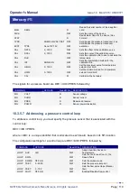
voltage is buffered by U15 and applied to the lower end of the reference resistor. The same
current thus passes through the sensor and the reference resistor.
U7 and U11 measure the voltage across the sensor and feed the inputs of ADC U12. The
outputs of U7 and U11 are also fed back to U10 and U15. This ensures that the voltage across
the sensor is exactly equal to the demand voltage generated by U24 and U25.
U13 and either U14 or U16 measure the voltage across the reference resistor. This differential
voltage is scaled by a reference gain multiplier, whose gain is selected to give an output in the
range 1 V to 2.5 V. This voltage is then passed to the reference voltage inputs of the ADC
(U12). This circuit configuration produces a ratiometric measurement technique. The resistance
of the sensor is:
Rsensor
=
Rref
x |
ADCnorm
| x
RefGain
/
ADCgain
Where:
Rref
is the reference resistance (either 2 kohms or 80 kohms).
ADCnorm
is the ADC reading, normalised to the range 0 to ±1 V.
RefGain
is the interpolated gain from the calibration tables.
ADCgain
is the gain setting of the ADC.
The measurement accuracy of this circuit does not depend on the accuracy of the excitation or
reference voltages. The accuracy primarily depends on the accuracy of the reference resistor
plus any errors introduced by operational amplifiers.
11.3.4 Calibrating the temperature measurement circuit
A block diagram of the temperature measurement circuit in calibration mode is given below.


