


Operator's Manual
Issue 14
/
Mar 2016 / UMC0071
Mercury
iPS
©2016 Oxford Instruments NanoScience. All rights reserved.
Page
47
UNIT CONFIGURATION
It is very important for normal operation of a Mercury iPS power
supply system that the configuration defined in the Config table and
Eng Config grouping tables correctly represents the actual
connections of the units. Incorrect operation and/or unit damage
may result if the configurations are incorrect.
UNITE CONFIGURATION
Il est très important pour le fonctionnement normal d'un système
d'alimentation Mercury iPS que la configuration définie dans le
tableau Config et Eng Config tables de regroupement représente
correctement les connexions réelles des unités. Une utilisation
incorrecte et / ou des dommages appareil peut entraîner si les
configurations sont incorrects.
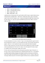
4.4.2 Limit(A)
This is the current limit for the group of power supply units configured in the group. It is the total
limit not the unit limit. For example, if the Z-axis group (GRPZ) is configured as a 180-10, (3
units in parallel) and if the limit current was set to 169.00A this would be a total limit of 169A
which would be 169/3 = 56.3333A limit for each unit. The group cannot ramp beyond 169A, so
if a demand set point was above this value the ramp would stop at 169A. If your magnet
needed 169A the current limit should be set slightly above this to compensate for slight over
shoots at the end of fast ramps. For example 169.1A or possibly even 169.5A.
4.4.3 Limit(V)
This is the voltage limit for the group of power supply units configured in the group. It is the total
limit not the unit limit. If the power supply measures a voltage greater than this limit at the
output terminal for a time period longer than the “Transient Time” (see below) the group will
enter QUENCH mode. The voltage limit should be set at a value above the maximum expected
output terminal voltage in normal use. So if the iPS was being used to energise a magnet with
a self-inductance of 35H to a current of 169A with a target ramp rate of 6A per minute and a
lead resistance of 10m
the maximum operational voltage would be 35*6/60 + 169*0.01 = an


