Operator Manual
Cha
pt
er
:
M
ai
nt
ena
nc
e
24
Do not cover the vents with cloths or other materials. Leave a space of at least 10 cm between the vents and the walls. The efficiency
of the Laser Welder could be compromised.
Replacing the mirror protection glass slide
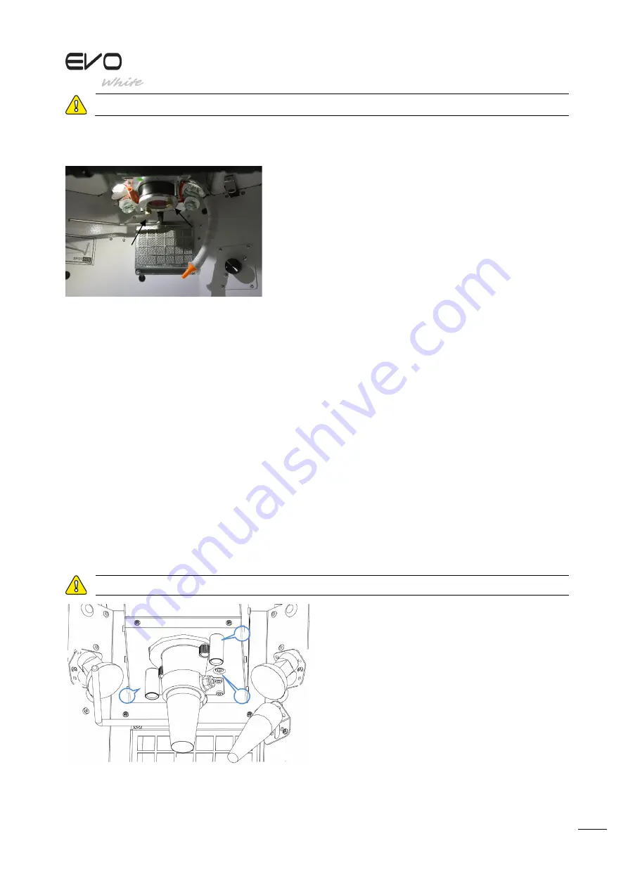
Check the status of the glass slide inside the welding chamber at least once a
month. To remove the glass slide support, loosen the 2 brass pawls indicated in
the photo. If the glass slide is marked by sprays of metal, is scratched, cracked or
broken, replace it with a new one (Code ATE00043).
Standard glass slide support
WARNING!
If the glass slide is very dirty, the power of the equipment may be reduced by up to 80% with respect to normal performance. If the
glass slide is damaged or broken, there can be serious consequences for the focal lens positioned above it.
Align the crosshair
WARNING!
Inspect the inside of the welding chamber only through the relevant window. Always keep the hands away from the path of the LASER
beam.
When the welding spot does not hit the centre of the crosshair, it can be corrected as described below:
Checking alignment
1.
Set the following parameters 1.0 KW, time 1.0 mS, frequency 0 Hz and minimum SPOT size.
2.
Position a piece of flat metal on the F
ocusing support plate (D2116466)
and perform a spot.
3.
Check the position of the spot with respect to the crosshair; if the spot intersects the crosshair in the centre, alignment is not required.
Correcting alignment
WARNING!
Take great care to avoid inadvertently activating LASER emission when performing realignment operations.
Correcting alignment
Take great care to avoid inadvertently activating LASER emission when performing realignment operations.
With the equipment in stand-by, locate the screws near to the glass
slide-holder cone, as shown in the figure.
Never touch the screw 3 positioned between the other two screws
without a guide. This screw is positioned by the manufacturer. Using
the 3 mm Allen key supplied, operate on screws 1 and 2.
•
Moving screw 1 shifts the welding point horizontally.
•
Moving screw 2 shifts the welding point vertically.
Use small movements and use small shots to verify correct positioning
of the crosshair on a piece of metal. Continue until the crosshair shot
coincides perfectly with the welding spot.
The alignment screws have brass guides to make them easier to
identify.
1
2
3


