


Port
Description
You Need:
USB
Provides USB3.0 connection
to the computer. The USB port
is hot pluggable, so you can
connect and disconnect USB
cables without affecting server
operations.
Installation media
Note: Maximum USB cable
length: 5 meters
Cable the Local Console
You can connect the Administration console to the local SER MGT (COM1) serial console
port. You can also operate the console using serial emulation over ILOM.
To cable a console connection:
•
Connect a serial console cable with an RJ-45 connector to the SER MGT port.
•
Connect ethernet to the ILOM port and use serial emulation.
When configuring boot loader parameters, set the Console Device to COM1. Never use
COM2 or VGA. The Oracle X7-2 server cannot boot the system when set to the default of
VGA. You must change this bootparameter when deploying over this platform.
Refer to the section "Change Boot Parameters by Interrupting a Boot in Progress" within the
Installation and Platform Preparation Guide to learn how to set your Console Device
bootparameter to "COM1". Refer to
(http://docs.oracle.com/cd/E93361_01/html/E93392/
gtibt.html)
to learn how to run an SSH session via iLOM using Virtual Serial Port Emulation.
Follow this procedure to cable your console:
1.
Locate the appropriate cables to connect to the Oracle X7-2.
2.
To cable a serial connection, insert the serial console cable into the SER MGT (COM1)
port.
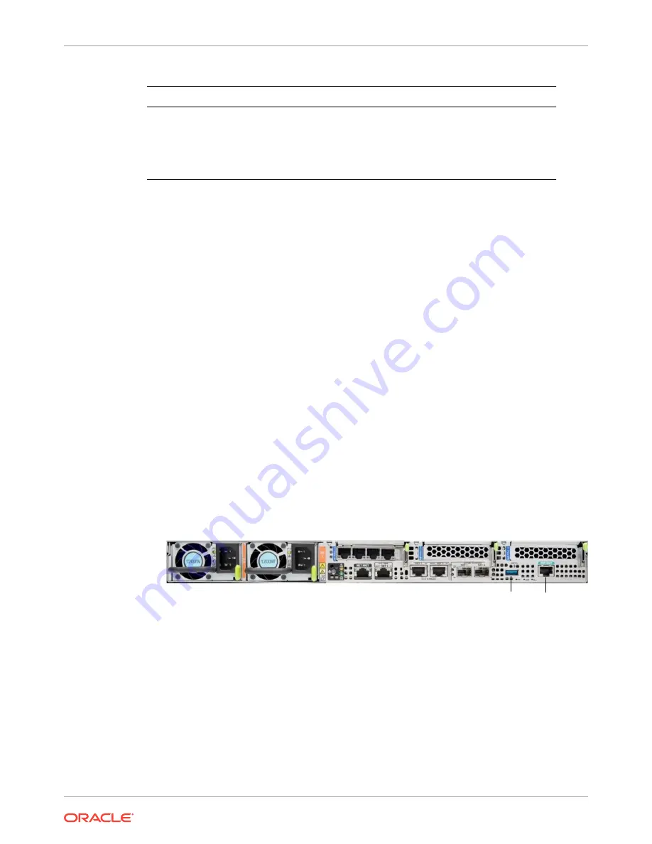
Figure 3-14 Connecting to USB and SER MGT (COM1) Ports
SER MGT
(COM1)
USB
3.
For installation procedures, insert the USB stick in the USB port.
4.
Lead the cables neatly away from the rear panel.
5.
Plug in the cables to their respective destination components.
Chapter 3
Cable the Oracle X7-2
3-11
Содержание netra X5-2
Страница 101: ...Chapter 7 Create and Deploy on Azure 7 35 ...
Страница 127: ...Figure 11 7 BMC Step 9 10 Click Next after the write operation is complete Chapter 11 Creating a Build Image 11 5 ...
Страница 151: ...Appendix A Acme Packet 6300 6350 Physical Interfaces A 12 ...
Страница 152: ...Note The Quad 10 GbE NIU must go in slot 0 Appendix A Acme Packet 6300 6350 Physical Interfaces A 13 ...


