H5CL
H5CL
156
H5CL-AD
j
-500
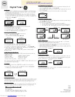
The cover conforms to finger protection standard against electric shock. (VDE 0106/P100)
DIN Track Mounting
120
H5CL-A
j
P2CF-11
64.5
47.5
7.5
58
48
Installation
Terminal Arrangement
AC Models
DC Models
Note:
1 and 6 are connected to each other internally.
8
10
9
7
5
4
3
2
5
4
3
Gate
Key protection
0 V
Reset
Start
12 to 24 VDC
Contact output
Transistor output
6
7
8
9
10
5
4
3
2
Reset
Start
Gate
Key protection
External power supply
12 VDC (50 mA max.)
11
1
8
9
11
Transistor output
Contact output
100 to 240 VAC
Input common (0 V)
6
1
--
+
Load
(Sensor)
(--)
(+)
Note:
Power supply circuit is insulated from the internal
circuit (or I/O).
Input Circuits
Start, Reset, and Gate Input
H5CL-A
j
(AC Models)
Key Protection Input
IN
V
in
-- 3.5V
(16V max.)
1 k
$
Internal circuit
V
in
: Supply voltage
H5CL-AD
j
(DC Models)
IN
+12 V
1 k
$
Internal circuit
IN
Internal circuit
+5 V
4.7 k
$
Note:
No key input is effective while
key protection input is ON.