background image

GT3W Series 

Timers

834 


www.idec.com

Switches & Pilot Lights

Display Lights

Relays & Sockets

Timers

Terminal Blocks

Circuit Breakers

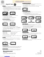
    GT3W Series — Dual Time Range Timers

Key features of the GT3W series include:

Sequential start, sequential interval, on-delay, recycler, 
and interval ON timing functions
2 time settings in one timer
8 selectable operation modes on each model
Mountable in sockets or fl ush panel
Power and output status indicating LEDs
Time ranges up to 300 hours


UL, c-UL Listed
File No. E55996


General Specifi cations

Contact Ratings

Operation System

Solid state CMOS Circuit

Allowable Contact Power

960VA/120W

Allowable Voltage

250V AC/150V DC

Allowable Current

5A

Maximum permissible 
operating frequency

1800 cycles per hour

Rated Load

1/8HP, 240V AC

3A, 240V AC (Resistive)

5A, 120V AC/30V DC 
(Resistive)

Conditional Short Circuit

Fuse   5A, 250V

Life

Electrical

100,000 op. minimum 
(Resistive)

Mechanical

20,000,000 op. minimum

Operation Type

Multi-Mode

Time Range

1: 0.1sec to 6 hours, 3: 0.1sec to 300 hours

Pollution Degree

2 (IE60664-1)

Over Voltage Category

III (IE60664-1)

Rated Operational Voltage

AF20

100-240V AC(50/60Hz)

AD24

24V AC(50/60Hz)/24V DC

D12

12V DC

Voltage Tolerance

AF20

85-264V AC(50/60Hz)

AD24

20.4-26.4V AC(50/60Hz)/21.6-26.4V DC

D12

10.8-13.2V DC

Disengaging Value of Input Voltage

Rated Voltage x10% minimum

Range of Ambient Operating Temperature

-10 to +50ºC (without freezing)

Range of Ambient Storage 
and Transport Temperature

-30 to +75ºC (without freezing)

Range of Relative Humidity

35 to 85%RH (without condensation)

Atmospheric Pressure

80kPa to 110kPa (Operating), 70kPa to 110kPa (Transport) 

Reset Time

60msec maximum

Repeat Error

±0.2%, ±10msec*

Voltage Error

±0.2%, ±10msec*

Temperature Error

±0.6%, ±10msec*

Setting Error

±10% maximum

Insulation Resistance

100MΩ minimum (500V DC)

Dielectric Strength

Between power and output terminals: 2000V AC, 1 minute
Between contacts of different poles: 2000V AC, 1 minute
Between contacts of the same pole:750V AC, 1 minute

Vibration Resistance

10 to 55Hz amplitude 0.75mm

2

 hours in each of 3 axes

Shock Resistance 

Operating extremes: 98m/sec

2

 (approx.10G) 

Damage limits: 490m/sec

(approx. 50G)

3 times in each of 3 axes

Degree of Protection

IP40 (enclosure), IP20 (socket)    (IEC60529)

Power Consumption 
(Approx.)

AF20

100V AC/60Hz

2.3VA

200V AC/60Hz

4.6VA

AD24 (AC/DC)

1.8VA/0.9W

Mounting Position

Free

Dimensions

40Hx 36W x 70 mm

Weight (Approx.)

72g


* For the value of the error against a preset time, whichever the largest applies.

Courtesy of Steven Engineering, Inc.-230 Ryan Way, South San Francisco, CA 94080-6370-Main Office: (650) 588-9200-Outside Local Area: (800) 258-9200-www.stevenengineering.com

Ready to Order?

Steven Engineering

Technical Question?

Summary of Contents for GT3W Series

Page 1: ... 20 4 26 4V AC 50 60Hz 21 6 26 4V DC D12 10 8 13 2V DC Disengaging Value of Input Voltage Rated Voltage x10 minimum Range of Ambient Operating Temperature 10 to 50ºC without freezing Range of Ambient Storage and Transport Temperature 30 to 75ºC without freezing Range of Relative Humidity 35 to 85 RH without condensation Atmospheric Pressure 80kPa to 110kPa Operating 70kPa to 110kPa Transport Reset...

Page 2: ...c 300 hours 100 to 240V AC 50 60Hz 8 pin GT3W A33AF20N 24V AC DC GT3W A33AD24N 1 For timing diagrams and schematics see page 836 2 For socket and accessory part number information see page 838 3 8 and 11 pin models differ only in the number of pins extra pins are not used 4 For the timing diagram overview see page 794 5 For details on setting time ranges see the instructions on page 837 Time Range...

Page 3: ...al No Item Power Delayed Contact Ry1 5 8 NC 6 8 NO 2 7 1 4 NC OUT1 1 3 NO OUT2 Set Time Description ON during T1 ON after T1 during T2 C Recycler and instantaneous T1 T2 Delayed Contact Ry2 Operation Indicator Terminal No Item Power Delayed Contact Ry1 5 8 NC 6 8 NO 2 7 1 4 NC OUT1 1 3 NO OUT2 Set Time Description Instantaneous ON OFF during T1 ON during T2 G Interval ON Delay T1 T2 Delayed Contac...

Page 4: ...and Caution Warning Warning notices are used to emphasize that improper operation may cause sever personal injury or death Turn power off to the Electronic timer before starting installation removal Wiring maintenance and inspection on the Electronic Timer Failure to turn power off may cause electrical shocks or fire hazard Emergency stop and interlocking circuits must be configured outside the Elec...

Page 5: ...afe Socket GT3A 1 2 3 11 pin GT3A 4 5 6 GT3D 1 2 3 11 pin GT3D 4 8 GT3F 1 2 11 pin GT3W 11 pin SR3P 05C 8 Pin Screw Terminal GT3A 1 2 3 8 pin GT3D 1 2 3 8 pin GT3F 1 2 8 pin GT3W 8 pin GT3S SR2P 06 SFA 202 11 Pin Screw Terminal GT3A 1 2 3 11 pin GT3A 4 5 6 GT3D 1 2 3 11 pin GT3D 4 8 GT3F 1 2 11 pin GT3W 11 pin SR3P 06 DIN Mounting Rail Length 1000mm BNDN1000 Installation of Hold Down Springs DIN R...

Page 6: ...hold down springs see page 838 Flush Panel Mount Adapter and Sockets that use an Adapter Accessory Description Appearance Use with Timers Part No Panel Mount Adapter Adaptor for flush panel mounting GT3 timers All GT3 timers RTB G01 Sockets for use with Panel Mount Adapter 8 pin screw terminal Shown SR6P M08G for Wiring Socket Adapter All 8 pin timers SR6P M08G 11 pin screw terminal All 11 pin time...

Page 7: ...2 2 Input Terminal Input Terminal correct In a transistor circuit for controlling input signals with its primary and secondary power circuits isolated do not ground the secondary circuit GT3 Series Timer Input Terminal Power Rectifier Circuit Circuit Insulating Transformer Connect the input signal terminals of the GT3A timers to Terminal No 2 only Never apply voltage to other terminals otherwise t...

Page 8: ...T3A 1 2 3 Transistor output equipment such as proximity switches and photoelectric switches can input signals if they are voltage current output type with power voltage ranges from 18 to 30V and have1V When the signal voltage switches from H to L a signal is input to the timer Transistor Transistor Output Circuit 2 5 6 7 Input Terminal Inputs GT3A 4 5 6 Start Input The start input initiates a time...

Page 9: ...Timer 8 Pin with SR2P 06 1 56 40mm 1 404 2 5 0 039 1mm 3 43 88mm Maximum WhenMountingonDINRail BNDN 3 59 92mm Maximum 0 507 13mm 0 702 18mm 0 858 22mm DINRail 0 039 1mm HDSpring SFA 202 64 2mm 36mm 1 23 31 7mm 2 34 60mm 0 066 1 7mm Digital GT3 Timer 11 Pin with SR3P 06 1 56 40mm 1 404 2 5 0 039 1mm 3 43 88mm Maximum WhenMountingonDINRail BNDN 3 59 92mm Maximum 0 507 13mm 0 702 18mm 0 858 22mm DINR...

Page 10: ...66 1 7mm 3 82 98mm Maximum WiringSocketAdapter 1 66 42 5mm Mounting Hole Layout Horizontal Close Mounting Single Mounting 45 45 45 48N 3 Tolerance 0 5 to 0 N No of timers mounted Analog and Digital GT3 Timer 8 Pin with SR6P M08G ø3 6 min 8 M3 5 Terminal Screw 2 1 8 7 3 4 5 6 6 9 max 30 4 44 6 Panel Thickness 0 8 to 5mm 80 5 7 9 8 3 44 6 3 5 max 5 6 min Analog and Digital GT3 Timer 11 Pin with SR6P...

Page 11: ...Ready to Order Steven Engineering Technical Question ...

Reviews: