background image

35

Adding and Deleting Subprograms

Section 4-6

2.

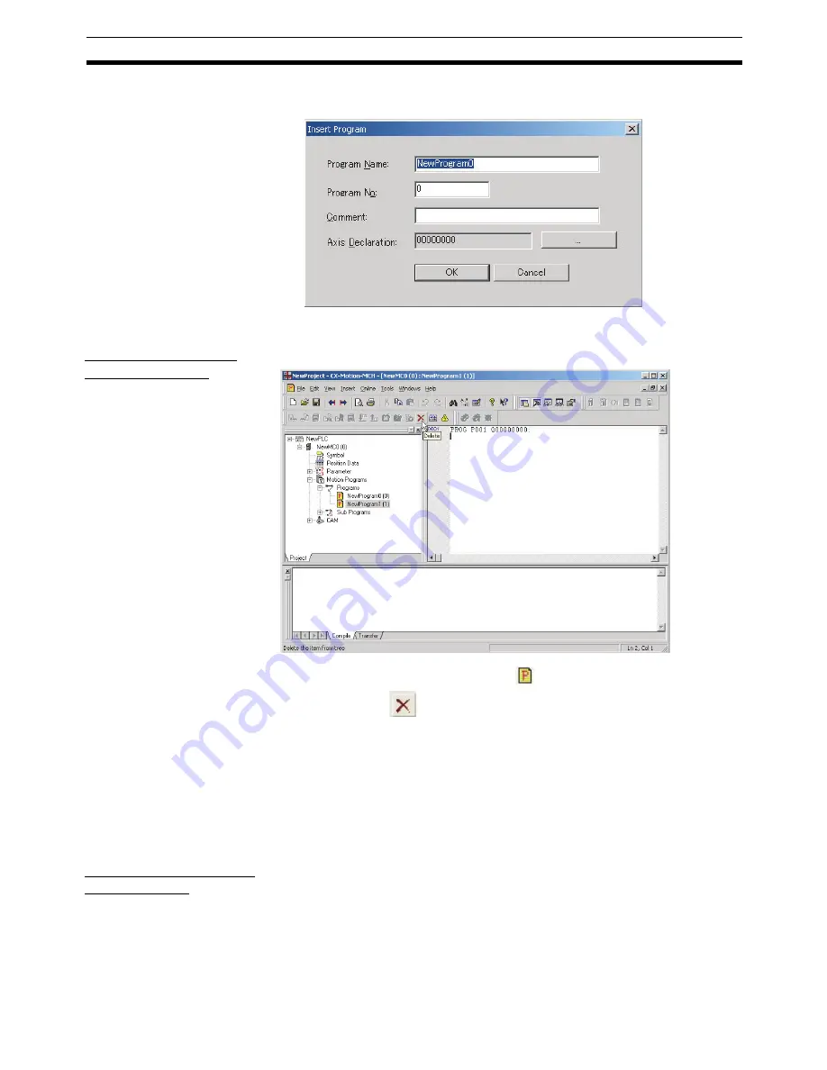
The Insert Program Dialog Box will be displayed. Set the program name,
program number, comment, and axis declaration.

3.

Click the 

OK

 Button. The individual program will be added to the MC Unit.

Deleting a Program 
from an MC Unit

The following procedure deletes a registered program from an MC Unit.

1,2,3...

1.

Select the unwanted program icon (

) in the project tree and select 

Edit

- Delete

, click 

 in the toolbar, or press the 

Delete

 Key. It is also possi-

ble to right-click the unwanted program icon and select 

Delete

 from the

pop-up menu.

2.

A dialog box will be displayed to confirm the deletion. Click the 

Yes

 Button

to delete the program. The selected program will be deleted from the pro-
grams registered in the MC Unit.

4-6

Adding and Deleting Subprograms

Adding a Subprogram 
to an MC Unit

The following procedure adds an individual subprogram to a project’s MC
Unit.

Individual subprograms can be added with program numbers from 500 to 599.

Содержание CX-MOTION - 06-2008

Страница 1: ...CX Motion MCH Cat No W448 E1 04 OPERATION MANUAL...

Страница 2: ...CXONE AL C V3 CXONE AL D V3 CX Motion MCH Operation Manual Revised June 2008...

Страница 3: ...iv...

Страница 4: ...n some OMRON products often means word and is abbreviated Wd in documentation in this sense The abbreviation PLC means Programmable Controller PC is used however in some Program ming Device displays t...

Страница 5: ...vi...

Страница 6: ...ng the Software 8 2 2 Connecting to a PLC 8 SECTION 3 Basic Operations 13 3 1 Basic Operations 14 3 2 Operations Listed by Purpose 25 SECTION 4 Creating Projects 29 4 1 Creating a New Project 30 4 2 A...

Страница 7: ...9 1 Switching to Monitor Mode 66 9 2 Test Run 67 9 3 Debugging the Program 69 SECTION 10 Data Traces 73 10 1 Data Traces 74 SECTION 11 Backup and Restore 77 11 1 Backup from MC 78 11 2 Restoring to M...

Страница 8: ...ix TABLE OF CONTENTS SECTION 15 Troubleshooting 93 15 1 Troubleshooting 94 15 2 Error Codes 101 Revision History 115...

Страница 9: ...x TABLE OF CONTENTS...

Страница 10: ...e MC Unit Operation Manual carefully and be sure you understand the information pro vided before setting up or using an application for a Motion Control Unit For details on procedures for installing t...

Страница 11: ...ween the personal computer and Motion Control Unit Servo Driver and to write data transferred to the Motion Control Unit to the Motion Control Unit s flash memory Section 8 provides information on mon...

Страница 12: ...ective media without charge If OMRON is unable to replace the defective media or correct the Software the liability of OMRON and the User s remedy shall be limited to a refund of the license fee paid...

Страница 13: ...other reasons EXTENT OF SERVICE The license fee of the Software does not include service costs such as dispatching technical staff ERRORS AND OMISSIONS The information in this manual has been carefull...

Страница 14: ...on MCH can find words in all pro grams The CX Motion MCH could com pare data with MC Units in detail The CX Motion MCH can compare data with MC Units in detail The CX Motion MCH can display comparison...

Страница 15: ...xvi Note All new functions can be used in Motion Control Units with unit version 3 0 or later...

Страница 16: ...s important for the safe and reliable application of the CX Motion MCH You must read this section and understand the information contained before attempting to set up or operate the CX Motion MCH 1 In...

Страница 17: ...operating the Unit Be sure to read this manual before attempting to use the Unit and keep this man ual close at hand for reference during operation WARNING It is extremely important that the CX Motion...

Страница 18: ...ng precautions when using the CX Motion MCH Confirm that the correct unit number is specified for the destination node before transferring parameters or other data to the Motion Control Unit Confirm t...

Страница 19: ...d operation Changing the operating mode of the PLC including changing the Star tup Mode Force setting force resetting any bit in memory Changing the present value of any word or any set value in memor...

Страница 20: ...of the CX Motion MCH and describes the functions and system configuration required to operate the CX Motion MCH Be sure to read this section before using the CX Motion MCH 1 1 What is the CX Motion MC...

Страница 21: ...Computers Refer to the CX One Ver 3 0 Setup Manual W463 for the computer system requirements for the CX Motion MCH Checking the Package Refer to the CX One Ver 3 0 Setup Manual W463 for details on the...

Страница 22: ...reating Transferring ladder program Monitoring File management etc Servo Driver Servomotor Servo Driver Servo Driver Servomotor External inputs External inputs Forward rotation limit input signal Reve...

Страница 23: ...position data programs and CAM data page 48 Printing Print Used to print various project data page 88 Online Initial setting Used to setup CPU Unit or MC Unit page 54 Communications setting Used to ma...

Страница 24: ...ction Used to set release protection on programs and cam data and select data items that can be read through the secondary password page 85 Switch User Used to switch the user page 86 Error Error log...

Страница 25: ...reating a New Project Adding MC Unit to Project Adding Tasks Axes Programs and CAM Data to MC Unit CX Motion MCH Basic Window Editing Transferring MC Unit s System Parameters Servo Parameters Position...

Страница 26: ...n installing the CX Motion MCH and CX Server and connecting to the PLC 2 1 Installing and Uninstalling the Software 8 2 2 Connecting to a PLC 8 2 2 1 Connecting to CS CJ series PLCs 8 2 2 2 Connecting...

Страница 27: ...eripheral port or RS 232C port on the PLC Note 1 The CS1W CN118 cable is used as a relay cable to connect the personal computer to the CPU Unit s peripheral port using the RS 232C cable model XW2Z as...

Страница 28: ...ection possible For CX Motion MCH it can also be connected to a modem SYSMAC WAY Host Link Used for communications with general host computers Slower than Toolbus Not only 1 on 1 connection but also 1...

Страница 29: ...AT compatible USB port A connector USB Commercially available USB 1 1 or 2 0 cable 5 m max IBM PC AT or compatible CP series CPU Unit USB port Commercially available USB cable Peripheral USB port Uni...

Страница 30: ...e XW2Z 200S CV 500S CV 2 m 5 m Uses anti static connec tor USB RS 232C IBM PC AT or compatible CJ2 CPU Unit USB port Commercially available USB cable USB port XW2Z 200S CV 500S CV Connecting Cable Ser...

Страница 31: ...12 Connecting to a PLC Section 2 2...

Страница 32: ...13 SECTION 3 Basic Operations This section describes each of the windows and basic operations 3 1 Basic Operations 14 3 2 Operations Listed by Purpose 25...

Страница 33: ...ned from the CX Programmer That Was Installed from the CX One 1 2 3 1 Right click a Motion Control Unit in the I O Table Window and select Start Special Application Start with Settings Inherited from...

Страница 34: ...corner of the window After editing a project if the project has not been saved the following dialog box will be displayed 2 Click the Yes Button to save the changes made Click the No Button if it is n...

Страница 35: ...shortcut Main menu Item Contents Keyboard shortcut File New Creates a new project file mnh Ctrl N Open Opens an existing project file mnh Ctrl O Close Closes the project file mnh Save Saves the activ...

Страница 36: ...ion pro gram or CAM data editing window Ctrl V Delete Deletes an MC Unit motion task axis motion program or CAM table Del Select All Selects all of the data displayed in the parameter data position da...

Страница 37: ...s hides the Program Toolbar Debug Displays hides the Debug Toolbar Windows Project Workspace Displays hides the Project Work space Window Alt 1 Output Win dow Displays hides the Output Window Alt 2 Ge...

Страница 38: ...ed con stants in the servo parameters editing window Sequence Related Constants Displays only the sequence related constants in the servo parameters editing window Other Con stants Displays only the o...

Страница 39: ...Transfers parameters and other data altogether to the MC Unit From All MC Transfers parameters and other data altogether from the MC Unit Write To Flash Saves the MC Unit s parameters and other data C...

Страница 40: ...o the previous win dow Alt Shift 0 Cascade Stacks the open editing windows Tile Horizontally Horizontally tiles the open editing windows Tile Vertically Vertically tiles the open editing win dows Help...

Страница 41: ...ect Workspace Window 2 Display hide the Output Window 3 Display hide the General Watch Window 4 Display hide the Debug Watch Window 5 Display hide the Status Monitor Window 6 Display the Properties Wi...

Страница 42: ...ndow 13 Delete 14 Switch between online offline 15 Switch between normal mode and monitor mode Number Function Number Function 1 Compile the program 2 Insert remove a break point 3 Remove all break po...

Страница 43: ...be displayed Displaying CX Motion MCH Version Information Select Help About CX Motion MCH The CX Motion MCH version informa tion will be displayed Number Function 1 Displays messages regarding the sta...

Страница 44: ...ubpro gram from a file Select Motion Programs Programs or the sub program and select File Import or right click and select Import Sub Program or Import 46 Exporting a subpro gram to a file Select the...

Страница 45: ...ct Edit Edit right click and select Edit or double click Ctrl E 42 Compiling a program Select the program or subprogram and select Edit Com pile or right click and select Compile F7 23 Editing a CAM t...

Страница 46: ...store Restore to MC 78 Verifying a backup file with the MC Unit Select the MC Unit and select Online Backup and Restore Verify Backup files with MC 79 Setting and changing passwords for protec tion Se...

Страница 47: ...28 Operations Listed by Purpose Section 3 2...

Страница 48: ...g MC Units tasks axes programs subprograms and CAM tables 4 1 Creating a New Project 30 4 2 Adding and Deleting MC Units 31 4 3 Adding and Deleting Tasks 32 4 4 Adding and Deleting Axes 33 4 5 Adding...

Страница 49: ...is being created a dia log box will be displayed for adding an MC Unit after setting the PLC model 1 2 3 1 On the CX Motion MCH Basic Window select File New press the Ctrl N Keys or click in the toolb...

Страница 50: ...C Unit s name model number and unit number unit number as a CPU Bus Unit in the Insert MC Dialog Box 3 Click the OK Button The MC Unit will be added to the project Deleting MC Units 1 2 3 1 Select the...

Страница 51: ...sert Task from the pop up menu 2 An individual task will be added to the MC Unit s Tasks folder Deleting a Task from an MC Unit The following procedure deletes a registered task from an MC Unit The lo...

Страница 52: ...rameter or Axes Icon in the project tree and select Insert Axis or click in the toolbar It is also possible to right click the Axes Icon and select Insert Axis from the pop up menu 2 The Insert Axis D...

Страница 53: ...to confirm the deletion Click the Yes Button to delete the axis The selected axis will be deleted from the axes regis tered in the MC Unit 4 5 Adding and Deleting Programs Adding a Program to an MC Un...

Страница 54: ...e project tree and select Edit Delete click in the toolbar or press the Delete Key It is also possi ble to right click the unwanted program icon and select Delete from the pop up menu 2 A dialog box w...

Страница 55: ...right click the Motion Programs or Sub Programs Icon and select Insert Sub Program from the pop up menu 2 The Insert Sub Program Dialog Box will be displayed Set the subprogram name subprogram number...

Страница 56: ...eted from the subprograms registered in the MC Unit 4 7 Adding and Deleting CAMs Adding CAM Tables to an MC Unit The following procedure adds individual CAM tables to a project s MC Unit Up to 32 CAM...

Страница 57: ...able icon in the project tree and select Edit Delete click in the toolbar or press the Delete Key It is also possible to right click the unwanted CAM table icon and select Delete from the pop up menu...

Страница 58: ...escribes the operations used to edit data This manual shows how to edit data but does not describe the functions of the data and parameters For details on the various data settings refer to the MC Uni...

Страница 59: ...e set for system parameters and variable addresses Those names can be used to reference parameters in the General Watch Window programs and subprograms Position Data Position data can be edited The na...

Страница 60: ...Tab and either double click the desired parameter or right click the desired parameter and select Edit from the pop up menu A new variable can be added by right clicking on the Variables Tab Page and...

Страница 61: ...ed either double click the desired MC Unit s servo parameters or select the desired MC Unit s servo parameters and press the Enter Key Editing Motor Settings Displaying the Window With the project tre...

Страница 62: ...ECTION 6 Saving and Reading Projects This section describes the operations used to save and read new projects 6 1 Saving a Project 44 6 2 Reading a Project 44 6 3 Importing Files 45 6 4 Exporting File...

Страница 63: ...e 1 2 3 1 Select File Save As The following window will be displayed 2 After entering the destination folder file name and file type click the Save Button Use the default file type mnh since the proje...

Страница 64: ...tem parameter or variable file under the Symbol Icon csv filename extension 1 2 3 1 Select the Symbol Icon in the project tree and either select File Import or click in the toolbar It is also possible...

Страница 65: ...d select Import Program or Import from the pop up menu Note When a file is imported to an individual program the existing program will be overwritten 2 Enter the program name program number and select...

Страница 66: ...csv filename extension 1 2 3 1 Select the CAM Icon or an individual CAM table icon in the project tree and either select File Import or click in the toolbar It is also possible to right click the CAM...

Страница 67: ...click the OK Button Position Data Files This procedure exports a position data file csv filename extension 1 2 3 1 Select the Position Data Icon in the project tree and either select File Ex port or...

Страница 68: ...ht click the individual subprogram icon and select Export from the pop up menu 2 Enter the destination folder file name and file type and then click the Save Button Multiple Program Subprogram Files T...

Страница 69: ...r and then click the Export Button CAM Data Files This procedure exports a CAM data file csv filename extension 1 2 3 1 Select an CAM table icon in the project tree and either select File Export or cl...

Страница 70: ...51 Exporting File Section 6 4 2 Enter the destination folder file name and file type and then click the Save Button...

Страница 71: ...52 Exporting File Section 6 4...

Страница 72: ...he Motion Control Unit to the Motion Control Unit s flash memory Note Be sure that the personal computer is connected to the PLC via a connecting cable and that online communications are established b...

Страница 73: ...SW4 to OFF and make appropriate setting of PLC Setup Set Programming Con sole Address 144 to its default 0000 Hex If the default setting has not been changed leave the setting as it is When using the...

Страница 74: ...ings in the Driver Tab Page Connecting to the PLC Select Online Work Online or click in the toolbar It is also possible to right click the PLC icon in the project tree and select Work Online from the...

Страница 75: ...tup 7 3 Transferring Comparing and Saving Data Transferring to the MC Unit 1 2 3 1 Select the MC Unit icon in the project tree and either select Online Trans fer To MC or click in the toolbar It is al...

Страница 76: ...hen the OK Button is clicked The progress of the transfer will be displayed as shown in the fol lowing diagram Transferring from the MC Unit 1 2 3 1 Select the MC Unit icon in the project tree and eit...

Страница 77: ...s shown in the following diagram Comparing Data with the MC Unit 1 2 3 1 Select the MC Unit icon in the project tree and either select Online Trans fer Compare or click in the toolbar It is also possi...

Страница 78: ...MC Win dow will be displayed showing the comparison results 4 Double click Position Data Programs Sub Programs or Cam data The following window will be displayed 5 Click the Overview Button to display...

Страница 79: ...ree and either select Online Write To Flash or click in the toolbar It is also possible to right click the MC Unit icon in the project tree and select Write To Flash from the pop up menu 2 Select the...

Страница 80: ...sfer To All MC or click in the toolbar It is also possible to right click the PLC icon in the project tree and select Batch Transfer To MC from the pop up menu 2 Select the destination MC Unit in the...

Страница 81: ...dow and select Range Transfer To MC from the pop up menu 2 The data of the selected Value will be transferred to the MC Unit Range Transfer MC Unit to Computer 1 2 3 1 Right click in the Edit Paramete...

Страница 82: ...axis s present position and variable values are displayed in the Monitor Windows Note Be sure that the computer and PLC are connected with the connection cable and the communications between them are...

Страница 83: ...Window can be used to check and change variable values excluding system variables Starting the General Watch Window Click in the toolbar If the CX Motion MCH is connected online monitoring will start...

Страница 84: ...Note Operation from Support Tool is supported for MC Units with unit version 3 0 or later 9 1 Switching to Monitor Mode 66 9 1 1 Starting Monitor Mode 66 9 1 2 Ending Monitor Mode 67 9 2 Test Run 67 9...

Страница 85: ...Unit in the project tree and then select Online Monitor Mode or click in the toolbar The following warning dialog box will be displayed Read the contents of the warning carefully Click the OK Button...

Страница 86: ...which to execute a test run in the Test Run Window 2 Click to lock the selected axis 3 To use an override select the Axis Override Option and enter the override set value Click the Set Button to writ...

Страница 87: ...gative direction JOG Jogs the axis in the positive direction Jogs the axis in the negative direction Origin Search Searches for the origin Origin Return Returns the axis to the origin Forced Origin Fo...

Страница 88: ...ter 9 3 1 Setting Break Points 1 2 3 1 Display the program to debug 2 Move the cursor to the step to set the break point and click A break point mark will be displayed 3 Click again the break point wi...

Страница 89: ...n the toolbar to debug the program one step at a time Note In the following case program execution will not stop at a breakpoint and will continue to the next break point The first break point is skip...

Страница 90: ...on buttons will operate the motor at the desig nated speed Execute the operation only after confirming safety 2 The operation on the personal computer may not stop the motor Provide an emergency stop...

Страница 91: ...72 Debugging the Program Section 9 3...

Страница 92: ...Traces This section describes the data trace function Note Data traces are supported for MC Units with unit version 3 0 or later 10 1 Data Traces 74 10 1 1 Executing a Data Trace 74 10 1 2 Changing th...

Страница 93: ...icon and select Work Online from the pop up menu It is also possible to click in the toolbar The CX Motion MCH will be connected to the PLC 2 Select the MC Unit icon in the project tree and then sele...

Страница 94: ...d the data trace is completed The MC Unit will transfer the results of the data trace to the CX Motion MCH auto matically and display them graphically 10 1 2 Changing the Graph Display 1 2 3 1 Select...

Страница 95: ...76 Data Traces Section 10 1...

Страница 96: ...e sure that the personal computer is connected to the PLC via a Connecting Cable and that online communications are established before backing up and restoring data Backing up and restoring data is su...

Страница 97: ...tering or selecting the destination folder file name and file type click the Save Button Use the default file type bkh because the MC Unit data is being saved in a CX Motion MCH backup file 11 2 Resto...

Страница 98: ...e Yes Button to start verifying 11 3 Verifying Backup File with MC Unit Use the following procedure to verify a backup file with an MC Unit 1 2 3 1 Select Online Backup and Restore Verify Backup file...

Страница 99: ...80 Verifying Backup File with MC Unit Section 11 3...

Страница 100: ...e PLC via a Connecting Cable and that online communications are established before setting or releasing read protection setting or changing passwords or switching the user Read protection is supported...

Страница 101: ...on the data that can be read To set protection set a primary pass word and a secondary password and then select the data items that can be read through the secondary password Read protection can be se...

Страница 102: ...and click the OK Button 3 After entering the new password and the confirm password click the Transfer PC to MC Button Note All programs and cam data cannot be read if the primary password is forgotte...

Страница 103: ...ords Section 12 2 5 Click the Yes Button to display the following window 6 Select Set Protection or Release Protection and the data items that can be read through the secondary password and then click...

Страница 104: ...tection 1 2 3 1 Select Online Read Protection Set Release Protection in online mode The following window will be displayed 2 Select Set Protection or Release Protection and the data items that can be...

Страница 105: ...t Online Read Protection Switch User in online mode The fol lowing window will be displayed to request entering the primary password in secondary normal user status The following window will be displa...

Страница 106: ...87 SECTION 13 Printing This section describes the operations used to print project data 13 1 Printing 88...

Страница 107: ...the zone parameters F Task Parameter All Print all of the motion task parameters Individual Print only the motion task parameters specified in the list G Axis Parameter All Print all of the axis para...

Страница 108: ...89 Printing Section 13 1 Printing the Error Log The Error Log can be printed To print the error log display the Error Log Window and select File Print from the Error Log Window s menu bar...

Страница 109: ...90 Printing Section 13 1...

Страница 110: ...91 SECTION 14 Error Log This section provides information on the error log generated by the MC Unit 14 1 Error Log 92 14 2 Error Codes 92...

Страница 111: ...atest error log information from the MC Unit The Clear All Button can be clicked to delete the error log Note Axis errors are not displayed in the error log 14 2 Error Codes Error Causes and Error Pro...

Страница 112: ...93 SECTION 15 Troubleshooting This section provides information on the troubleshooting methods for the MC Unit 15 1 Troubleshooting 94 15 2 Error Codes 101...

Страница 113: ...isplayed Is the cable between the computer and PLC connected correctly Is the connected PLC turned ON Was the I O table created after the MC Unit was mounted Is another Programming Device that uses CX...

Страница 114: ...CX Server is currently processing the maximum number of requests This error indicates the application is thrashing the maximum possible communications throughput of the device s connection The CX Serv...

Страница 115: ...drive This error occurs when Servo drive is not connected Mismatch of axis numbers in project and the servo drives connected to MC Unit Series or models in the project and servo drive are different 1...

Страница 116: ...ive model and version with the connected Driver 8451 Cannot register nor write 1 The program capacity has been exceeded 2 The CAM data capacity has been exceeded 3 Writing to flash memory is not pos s...

Страница 117: ...respond to the com mand 10 Too Many Arguments The total number of operands exceeded 11 The number of axes to respond to the command has exceeded the number of programmable axes The total number of va...

Страница 118: ...d Neither hexadecimal operand parameters nor axis parameter values have been set The hexadecimal digit number has exceeded eight digits The acronym followed by was not S M C O T A or I The hexadecimal...

Страница 119: ...irection Error MOVEC Q Rotation direction has exceeded the limit 37 NSTOP Mismatch Error Other data for axes and operands has been set before the NSTOP command 38 Q argument of PROG is missing No oper...

Страница 120: ...main board and sub board 0005h 0005h WDC error was generated between the main board and sub board Internal HW WDT error 0006h 0006h Internal HW WDT error Sub board code error 0013h 0013h System code a...

Страница 121: ...at it does not overlap with the area used for the file memory function and restore the power Name Error log Alarm code Cause and remedy Error code Detail code Name Error log Alarm code Cause and remed...

Страница 122: ...ogram to call the subprogram after the block currently using the axis is completed Axis alarm generated 2008h 2008h An alarm has occurred in an axis controlled by a task Remove the cause of the axis a...

Страница 123: ...exceeded the limit C WORK OFFPOS E S CAM CAMBOX FOR Correct the applicable operands With CAM CAMBOX This error occurs when setting the operands as Starting data number Ending data number or when sett...

Страница 124: ...owable range When specifying with variables check if the substitution for mula is correct The radius has exceeded 2147483647 Check the program and correct the setting value so that it will not exceed...

Страница 125: ...is from multiple rows in the program Axis movement command was executed on the axis which is in syn chronous execution as a slave axis Correct the program so that any axis movement command will not be...

Страница 126: ...on virtual axes and I O axes Correct the program LATCH The contents of 900Ah Positive latch enabled range and 900Bh Negative latch enabled range in the motor parameters are not written correctly After...

Страница 127: ...el signal ON Move the axis in the positive direction manually Over travel both direc tions 3004h 3004h The over travel signals in both directions have turned ON during axis movement or when the axis w...

Страница 128: ...com mand Do not execute Servo Unlock during axis movement Synchronous communica tions alarm 300Ah 300Ah An error was occurred in the MECHATROLINK synchronous com munications The followings are the pos...

Страница 129: ...ues related to B A were changed Note B No of encoder pulses P5AA05 A P5AA04 P5AA06 B A is integer calculation and the result is to be reduced After the change was made saving to F ROM restore the powe...

Страница 130: ...the origin search start direc tion And check and correct the positions of the origin proximity limit switch and the limit switch Synchronous slave axis speed over 3011h 3011h With synchronous commands...

Страница 131: ...Z of the encoder Breakage of encoder cable Too small distance between the origin proximity limit switch and the limit switch These causes are to be removed Excessive speed com mand 037Ah 0399h 3019h...

Страница 132: ...5 2 MLK Device Alarm Codes Name Error log Cause and remedy Error code Detail code Depending on the device 037Ah to 0399h 4000h Alarm code of each device Depending on the device Follow the directions o...

Страница 133: ...114 Error Codes Section 15 2...

Страница 134: ...d program debugging functions added to online operations and data trace function added Page 6 Version upgrade information added Pages 12 and 13 Procedures altered Page 13 Program and Debug commands ad...

Страница 135: ...age 8 Heading added Page 9 Section added Pages 15 and 18 Row added for Find in Programs Pages 17 and 24 Rows added for Backup and Restore and Read Protection Page 18 Toolbar illustration replaced Page...

Отзывы: