


3-1
S E C T I O N 3
PC Board and Keypad Mounting
• • • • • • • • • • • • • • • • • • • • • • • • • • • • • • • • • • • • • • • • • • •
Mounting the OMNI-624/OMNI-624EU PC Board
NOTE: The door of the metal cabinet may be removed to make it easier to install the control panel.
Remove the door as follows:
1. With the cabinet laying on a flat surface, swing open the door to its full-open position.
2. Slide the door out of its retaining slots in the cabinet and store in a safe place.
BEFORE MOUNTING PRINTED CIRCUIT BOARD, BE CERTAIN THAT APPROPRIATE METAL
KNOCKOUTS HAVE BEEN REMOVED FROM THE METAL CABINET. DO NOT ATTEMPT TO REMOVE
THE KNOCKOUTS AFTER CIRCUIT BOARD HAS BEEN INSTALLED.
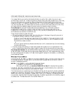
3. Insert top of circuit board into slots at top of cabinet. Make sure that circuit board rests in slots as
indicated in the diagram shown below.
4. Swing base of circuit board onto the raised cabinet tabs.
5. Secure the sides of the PC board to the enclosure using the 2 screws provided.
CABINET
DETAIL C
ANTENNA AND GROUNDING LUG INSTALLATION
ANTENNA
MOUNT
(2 PLACES)
ANTENNA
(2)
SCREW
(2)
BOARD
SUPPORTING
SLOTS
RCVR BRD
DETAIL A
SIDE VIEW
OF BOARD
SUPPORTING SLOTS
DETAIL B
SIDE VIEW
OF MOUNTING
SCREW
GROUNDING
LUG
(2)
pcb_mount-006-V0
CIRCUIT BOARD
CABINET
CONTROL CIRCUIT BOARD
+
+
CONTROL CIRCUIT BOARD
RF
RECEIVER
ANTENNAS
(INSERT IN
RIGHT-HAND
TERMINALS)
RF
RECEIVER
Содержание OMNI-624
Страница 6: ...vi...
Страница 100: ...OMNI 624 OMNI 624EU Installation and Setup Guide 8 8...
Страница 102: ...OMNI 624 OMNI 624EU Installation and Setup Guide 9 2...


