background image

710.1759.01.01-00D 


19/09/2018 


12 


Never touch any part of the refrigerant circuit when the cooler is running! 

14)


Because  the  pump  starts  up  immediately,  make  sure  that  the  direction  of  rotation  for  the  pump  matches  the 
direction of the arrow on the casing. If it is rotating in the opposite direction, turn off the main switch of the cooler 
immediately and arrange for the polarity of the cooler to be reversed.  

15)


After  a  few  minutes  carefully  open  the  filler  screw  again  in  order  to remove  any residual  air.  Tighten  the  screw 
again afterwards.  

16)


Wait  until  the  cooler  has  attained  the  operating  conditions.  This  is  indicated  when  the display shows  the  preset 
working range.  

17)


Check whether the pressure shown is within the limits specified for the pump. If not, take appropriate action to 
ensure that pump is able to run within the specified limits.  

18)


Check the level in the tank and top up with cooling medium if required. Fasten the tank cap afterwards. 

19)


Check the inside of the cooler and the piping system for leakage or loose connections. 

20)


Fit the front panel and the two side panels back onto the casing. 

21)


Check  the  preset  target  value.  The  water  cooler  is  normally  factory-set  to  the  temperature  required  by  the 
customer.  

22)


When the cooler is within the operating conditions set by the manufacturer, check whether the current uptake of 
the  cooler  matches  the  data  indicated  on  the  identification  plate  and  those  contained  in  the  table  in  the 
supplement. 

 
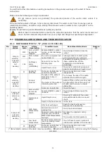
6.2   OPERATING SETTINGS OF THE ELECTRONIC CONTROLLER 


All operations must be carried out by qualified personnel only. 

The water cooler is supplied pre-adjusted for normal operating conditions and normally does not require 
any  modifications,  except  for  the  setting  the  temperature  of  the  cooling  medium  to  the  desired  value. 
Checking and any possible adaptation of the operating parameters is carried out via the controls on the 
front  of  the  water  cooler  and  via  the  control  panel.  The  water  coolers  are  equipped  with  an  operating 
thermostat to maintain the cooling medium temperature at a constant value. 


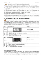
Type 

Controller display 

Models 

Type A 


CHA 1.3 to CHA 129 

S

y

m

b

o

le


Fan enabled (ON) – Programming Phase (flashes) – Anti-short cycle delay enabled 
(flashes) 


Defrost enabled (ON) – Programming Phase (flashes) 

AUX


Second relay ON (ON) 


A temperature alarm happened (ON) 


Type 

Controller display 

Models 

Type D 


CHA 1.3 to CHA 129


S

y

m

b

o

ls


Regulation enabled (ON) – Anti-short-circuit delay active (flashes) 


Degrees Celsius (ON) – Programming phase (flashes) 

AUX


Second relay active (ON) 


A temperature alarm has been triggered (ON)


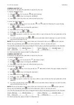
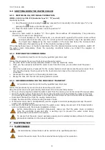
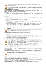
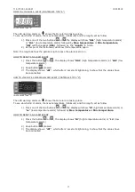
6.2.1   ELECTRONIC CONTROLLER 


The operating thermostat is supplied in a pre-adjusted state according to the standard specifications of 
the  water  cooler  listed  in  the  supplement.    The  operating  thermostat  controls  both  the  temperature 
adaptation functions and the other safety parameters (e.g. alarm management and the running time of 
the electric motors). The complete list of parameters in not supplied to the customer because changes in 
certain parameters may lead to problems affecting the reliability and characteristics of the water cooler. 


Содержание CHA 1.3

Страница 1: ...voda voda CHA 1 3 to a CHA 129 English User and Maintenance Manual e tina Manu l k provozu a dr b Save These Instructions Tyto pokyny si uschovejte O M I srl Via dell Artigianato 34 Fogliano GO 34070...

Страница 2: ...ONNECTION 9 6 OPERATION 10 6 1 CHECK LIST FOR THE INITIAL START UP OF WATER WATER HEAT EXCHANGER SYSTEMS 10 6 1 1 CHECK LIST MODELS CHA 1 3 11 10 6 1 2 CHECK LIST MODELS CHA 24 60 11 6 1 3 CHECK LIST...

Страница 3: ...ion prevents the pump and other circuits parts damages The use of a water cooler is recommended for treatment of liquids in industrial civil or commercial cooling 2 GENERAL SAFETY INSTRUCTIONS SYMBOLS...

Страница 4: ...he electricity mains in accordance with the standard EN 60204 and must ensure compliance with all other applicable national standards Fire The electricity supply must be disconnected in the event of f...

Страница 5: ...water cooler cannot be switched on again until the cooling medium has been filled up to the MAX mark on the level display RA Tank heating The tank heating system warms up the water in the tank It can...

Страница 6: ...e of the cooling medium according to the preset value The temperature controller with digital display is integrated in the door of the switch cabinet Fault messages are displayed on the temperature co...

Страница 7: ...84 1 CHA 110 1325 760 1400 300 300 635 300 84 2 1 2 CHA 129 1325 760 1400 300 300 635 300 84 2 1 2 4 TRANSPORT PACKING STORAGE 4 1 REMOVING THE WATER COOLER FROM PACKAGING AND HANDLING Each water coo...

Страница 8: ...fumes dust or inflammable vapors with non explosive atmosphere and in any case free of any element that may affect its correct functioning A suitable area to ensure a constant temperature in all seaso...

Страница 9: ...ove the water cooler from the circuit switch it off or use it in different ways at the same time A pipeline system with integrated filter near the water cooler to protect the pump against solid matter...

Страница 10: ...the upright up to the gland on the base of the switch cabinet CHA 99 to CHA 129 Inside the switch cabinet lay the cable in the installation duct up to the main switch where it is connected directly C...

Страница 11: ...tion of the arrow on the casing If it is rotating in the opposite direction turn off the main switch of the cooler immediately and arrange for the polarity of the cooler to be reversed 14 After a few...

Страница 12: ...the supplement 6 2 OPERATING SETTINGS OF THE ELECTRONIC CONTROLLER All operations must be carried out by qualified personnel only The water cooler is supplied pre adjusted for normal operating condit...

Страница 13: ...de Meaning Standard value Set Set point 15 Hy Differential 3 For others parameters please contact the Manufacturer CONTROLLER TYPE D Instructions for changing the parameters required by the user To mo...

Страница 14: ...rcuit by closing the stop valves for the feed and return lines at the inlet and outlet as necessary Disconnect the machine from the cooling medium lines Empty the tank and the internal cooling medium...

Страница 15: ...tly isolate it from the electricity mains Disconnect the power cable Open the bypass valves if present for the liquid circuit and isolate the water cooler from the circuit by closing the stop valves f...

Страница 16: ...low too low Check right rotation of pump and possible obstruction on liquid circuit P1 Sensor P1 defective Probe can be defective or not well connected Check connection and in case change probe 2 Pump...

Страница 17: ...tton or the display shows HAL high temperature alarm or LAL low temperature alarm 2 Keep button pressed 3 The display shows rST which after 2 sec starts lightening to show that the values have been ca...

Страница 18: ...LSK OKRUH 25 5 2 2 P IPOJEN K ELEKTRICK ENERGII 25 6 PROVOZ 26 6 1 KONTROLN SEZNAM PRO PO TE N SPU T N V M N K TEPLA VODA VODA 26 6 1 1 KONTROLN SEZNAM PRO CHA 1 3 A CHA 11 26 6 2 PROVOZN NASTAVEN PRO...

Страница 19: ...ktrick ochrana zabra uje po kozen erpadla a dal ch st obvodu Pro pravu kapalin v pr myslov m civiln m nebo komer n m chlazen se doporu uje pou it chladi e vody 2 OBECN BEZPE NOSTN POKYNY SYMBOLY POU V...

Страница 20: ...hladic jednotka je vybavena hlavn m vyp na em Autorizovan mont n technik se mus postarat o to aby byla chladic jednotka p ipojena k p vodu elektrick ho proudu v souladu s normou EN 60204 a mus zajisti...

Страница 21: ...erpadla se vypnou Chladic syst m nelze znovu zapnout dokud nebude chladic m dium dopln no na MAXIM LN hranici na ukazateli hladiny RA Vyh v n n dr e Vyh v n n dr e oh v voda v n dr i Slou k dosa en op...

Страница 22: ...venou hodnotou Teplotn dic jednotka s digit ln m displejem je integrov na do dv ek sp nac sk n Chybov zpr vy se zobrazuj na teplotn dic jednotce v podob k d 3 4 2 DOPL KY ELEKTRICK OBVOD P ipojen kabe...

Страница 23: ...ADOV N 4 1 ODSTRAN N BALEN A MANIPULACE S CHLADIC JEDNOTKOU V echny chladic jednotky se dod vaj v zes len m kartonov m obalu na d ev n palet Chladic jednotka se mus za v ech okolnost nach zet ve vzp m...

Страница 24: ...Je nutn naj t vhodnou oblast ve kter teplota nebude klesat pod 2 C a rozhodn pak nesm p esahovat 40 C v dn m ro n m obdob kdy bude stroj v provozu Pokud chcete provozovat chladic jednotku p i teplot...

Страница 25: ...j vypnut nebo pou it jin m zp sobem Potrubn syst m s integrovan m filtrem pobl chladic jednotky k ochran erpadla p ed pevn mi sticemi a k zabr n n usazov n materi lu na tepeln ch v m n c ch Doporu en...

Страница 26: ...ou st sm rem k pr chodce na z kladn sp nac sk n CHA 99 CHA 129 Uvnit sp nac sk n polo te kabel do instala n ho veden k hlavn mu vyp na i ke kter mu se p ipojuje p mo Zkontrolujte zda jsou rouby na svo...

Страница 27: ...pn te hlavn vyp na na chladic jednotce a zajist te aby se polarita chladic jednotky p evr tila 15 Po n kolika minut ch znovu opatrn otev ete plnic roub a odstra te p ebyte n vzduch Pot roub znovu dot...

Страница 28: ...ELEKTRONICKOU DIC JEDNOTKU Ve ker pr ce na chladic jednotce sm j prov d t pouze odborn pracovn ci Chladic jednotka se dod v v nastaven pro norm ln provozn podm nky a obvykle nen nutn na n prov d t dn...

Страница 29: ...d V znam Standardn hodnota K d V znam Standardn hodnota Set Bod nastaven 15 Hy Diferencial 3 Ohledn ostatn ch parametr se obra te na v robce TYP DIC JEDNOTKY D P i zm n hodnoty BODU NASTAVEN postupuj...

Страница 30: ...stupu Odpojte stroj od veden chladic ho m dia Vypr zdn te n dr a vnit n okruhy chladic ho m dia 6 3 3 VY AZEN Z PROVOZU ZA ELEM P EPRAVY Ve ker pr ce na chladic jednotce sm j prov d t pouze odborn pra...

Страница 31: ...okud jsou p tomny okruhu kapaliny a izolujte chladic jednotku od okruhu t m e dle pot eby uzav ete ventily na p vodn m a v stupn m veden na vstupu a v stupu Odpojte chladic jednotku od veden chladic h...

Страница 32: ...nebo nen spr vn p ipojena Zkontrolujte p ipojen a p padn vym te sondu 2 erpadlo nefunguj elektromag netick ventil funguje erpadlo je zablokovan Zuby erpadla jsou zablokovan prachem nebo koroz Pokuste...

Страница 33: ...displeji zobraz HAL alarm vysok teploty nebo LAL alarm n zk teploty b Udr ujte tla tko stisknut c Na displeji se zobraz rST kter za ne po 2 sekund ch blikat a t m d najevo e hodnoty byly zru eny JAK V...

Страница 34: ...dchylka V 5 pro uveden hodnoty Standard operating conditions standardn provozn podm nky 10 2 HYDRAULIC CIRCUIT DATA VLASTNOSTI ERPADLA A N DR E Model Model Circulation pump Ob hov erpadlo Circulation...

Страница 35: ...a speci ln ch modelech chladic ch jednotek kter jsou dostupn na vy d n Propylene Glycol mixture Sm s propylenglykolu Glp 0 10 15 20 25 30 35 40 45 50 Tc C 0 3 5 7 10 13 17 21 26 32 Re 100 100 98 96 94...

Страница 36: ...PUMP 1 2 FUSES POJISTKY ERPADLA 1 2 SICHERUNG PUMPE 1 2 FUSIBILES BOMBA 1 2 FR1 2 HEATER 1 2 FUSES POJISTKY OH VA E 1 2 SICHERUNG KURBELWANNENHEIZUNG 1 2 FUSIBILES RESISTENCIA 1 2 FRA TANK HEATER FUS...

Страница 37: ...EMPERATURA ALTA SC HEAT EXCHANGER Tepeln v m n k W RMETAUSCHER INTERCAMBIADOR DE CALOR SCV FAN CONTROL PROBE Sonda zen ventil toru DRUCKAUFNEHMER VERFL SSIGUNGSDRUCK SONDA VENTILADOR SF VENT Otvor ENT...

Страница 38: ...Kapalina 8 Customer Spot ebitel 5 55 Ambient air Okolni vzduch Atm Customer Spot ebitel 2 40 13 INDIVIDUAL SPECIFICATION INDIVIDU LN SPECIFIKACE You will find the individual specification for the unit...

Отзывы: