710.1759.01.01-00D
19/09/2018
9
5.2 ASSEMBLY (CONNECTIONS)
5.2.1 CONNECTION TO THE REFRIGERANT CIRCUIT (CONSUMER CIRCUIT)
All operations must be carried out by qualified personnel only.
Procedure:
-
In closed systems, make sure that the maximum obtainable cooling medium pressure in
the supply line does not cause a higher pressure level than the maximum permitted for
the water cooler.
-
Check the cleanliness of the supply line and the piping system to be connected.
-
Connect the water cooler with the consumer circuit; the identification of the joints
(cooling medium inlet/outlet) is indicated on the water cooler by means of the symbols
described in the introduction to the manual.
-
Make all the connections, without rotating the sleeves located on the hose.
The cooling medium circuits of the Series CHA with tank are open to the atmosphere as
standard.
Use piping, connections and fastening components with a cross-section to match the capacity of the
water cooler and the possible volume flow. This should not be smaller than the diameter of the water
cooler connections.
In the case of rigid connections, check during the initial start-up of the water cooler that it is not subject
to any vibrations that might endanger the integrity of the components.
We also recommend that you should plan to install the following system components:
♦
A bypass system with suitable valves upstream and downstream of the water cooler. This is
intended to allow use of the consumer circuit if you have to remove the water cooler from the
circuit, switch it off or use it in different ways at the same time.
♦
A pipeline system with integrated filter near the water cooler to protect the pump against solid
matter and avoid deposits on the heat exchangers. The recommended mesh width for the water
coolers is 25
µ
with a maximum pressure loss at the filter of 1 bar.
♦
In the models without flow monitoring, we suggest that you should install such a component if
the system exhibits losses or very high cooling medium consumption due to evaporation or
intervention by the operator. A further reason may be triggering of the solenoid valve to shut
down the system. The flow meter may trigger an alarm and enable immediate operator
intervention.
♦
On no account may the total pressure loss of the system exceed a value above that of the pump
performance.
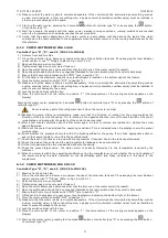
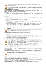
A Male-male fitting
B From the loading line
C To supply line
D “T” fittings
E Outlet water cooler fitting
5.2.2 ELECTRIC CONNECTION
The features of the main (size, protection system, ground connection) must comply with the Legislation
in force in the destination country, in relation to the electric features of the water cooler.
Below are the main general installation prescriptions.
All operations must be carried out by qualified personnel only.
The mains supply should be established with a rubber sheathed line connected to a TN-C system with
direct earthing.
230 V version (1 phase):
Connection with a single-phase, three-wire system (1/N/PE AC). The phase conductor and the neutral
conductor must be connected directly to the main switch of the water cooler.
The protective earth conductor must be connected to the earthing point of the water cooler.
Fig.1


