CAP.5
FUNZIONAMENTO E USO
I comandi attraverso i quali si utilizza il solle-
vatore sono:
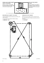
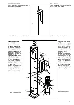
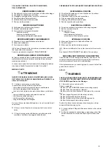
INTERRUTTORE GENERALE (QS Fig.59)
POSIZIONE 0: il sollevatore non é in tensio-
ne, é possibile l’accesso all’interno del qua-
dro; é altresì possibile lucchettare l’interruttore
per impedire l’uso del solllevatore.
POSIZIONE 1: dà tensione al motore del sol-
levatore ma ,se usato individualmente, non
permette di eseguire manovre ,e blocca la
porta del quadro contro aperture accidentali.
PULSANTE DI SALITA (SB1 Fig.59)
Tipo “uomo presente”, tensione 24V; se pre-
muto aziona la pompa della centralina idrauli-
ca.
Fig.60
PULSANTE DI DISCESA (SB2 Fig.59)
Tipo “uomo presente”, tensione 24V; se premuto aziona i magneti
di sgancio dei martelletti di sicurezza e l’elettrovalvola di discesa
della centralina idraulica.
PULSANTE DI STAZIONAMENTO (SB3 Fig.59)
Tipo “uomo presente”, tensione 24 V; se premuto aziona l’elettro-
valvola di discesa della centralina idraulica.
PULSANTE DI AVVIO (SB8)
Se premuto da tensione al trasformatore.
SOLLEVAMENTO
Ruotare l’interruttore generale (QS) in posizione 1 e premere il pul-
sante di salita fino al raggiungimento dell’altezza desiderata.
Durante la corsa, la leva di comando martelletti resta in trazione e
pertanto i martelletti rimangono disinseriti
STAZIONAMENTO
In condizioni di stazionamento il carico non deve MAI essere so-
stenuto dalle funi portanti, ma dai martelletti di stazionamento che
quindi devono essere automaticamente inseriti nelle asole delle
aste di sicurezza.
Una volta raggiunta l’altezza desiderata premere il pulsante di sta-
zionamento (SB3).
L’arresto del movimento avviene automaticamente allorché i mar-
telletti si appoggiano sul piano della prima asola che incontrano
durante la discesa.
DISCESA
Premere il pulsante di discesa (SB2) che, dopo una breve salita,
sgancia automaticamente i martelletti ed aziona l’elettrovalvola di
discesa.
La discesa verrà arrestata dal microinterruttore di discesa.
Per completare la discesa bisogna rilasciare il pulsante SB2 e pre-
mere il pulsante SB3, questa parte della discesa viene accompa-
gnata da un segnale acustico che avverte del pericolo di schiaccia-
mento dei piedi.
Se durante la discesa la piattaforma incontra un’ostacolo che im-
pedisce il proseguimento della corsa si ha l’intervento dei sensori
che azionano i micro di sicurezza allentamento funi con conse-
guente arresto del movimento.
In questa situazione é possibile comandare solo la salita. Durante
la fase di discesa la sicurezza contro l’accidentale caduta del vei-
colo é sempre assicurata dal martelletto comandato dal sensore
allentamento funi.
CHAPTER 5
OPERATING
PRINCIPLES AND USE
The lift operator controls are:
MAIN SWITCH (QS Fig.59)
POSITION 0: the lift is not connected to the
electrical supply; you can open the control pa-
nel and install a lockout on the main switch to
prevent unauthorised use of the unit.
POSITION 1: the lift motor is receiving electrical
power, but this button if used individually don’t
allow any lift operation.The door of the control
panel is locked and cannot be opened inadver-
tently.
LIFT BUTTON (SB1 Fig.59)
“Operator present” type, 24 V; when the LIFT
button is pressed the hydraulic control unit will
start up.
LOWERING BUTTON (SB2 Fig.59)
Also this button is “operator present” type, 24V; when pressed, it
activates the release magnet of the safety wedges and the lowe-
ring solenoid valve of the hydraulic control unit.
STOP BUTTON (SB3 Fig.59)
Operator present” type, 24 V; pressing the STOP button activates
the lowering solenoid valve in the hydraulic control unit.
PULSANTE DI AVVIO (SB8)
If you press this button it gives electrical power to the transformer.
LIFTING
Set the main switch ( QS ) to 1 and press the LIFT button until the
lift reaches the desired height.
During its travel, the safety wedge release lever will remain in trac-
tion so that the wedges keep disconnected.
STOPPING
When a vehicle is stopped in the elevated position, the load must
NEVER
be supported by the lift cables, the load must instead be
supported by the stopping wedges which must therefore be enga-
ged automatically in the slots on the safety rods.
When you reach the desired height press the STOP button (SB3).
The movement will be halted automatically as soon as the wedges
encounter the first safety rod slots during the initial lowering.
LOWERING
Press the lowering button (SB2) which, after a short rise, automati-
cally disengages the safety wedges and activates the lowering so-
lenoid valve.Lowering will be stopped by lowering microswitch. In
order to complete the lowering, the push button (SB2) will have to
be released and push button (SB3) will have to be pressed. In the
last part of the lowering an audible alarm will be heard to prevent
from foot treading danger.
If the platform should encounter an obstruction during its lowering
the sensors that activate the lift cable slack safety microswitches
will operate and stop the lowering movement.
In this situation only the LIFT control is accepted. Note that during
lowering cycles protection against the accidental falling of the vehi-
cle is provided by the safety wedge controlled by the lift cable slack
sensor (mechanical operation).
34
QS
SB2
SB1
SB3
SB8
Содержание 528C
Страница 1: ...I PONTE SOLLEVATORE A 4 COLONNE GB 4 POST LIFT 528C...
Страница 2: ......
Страница 13: ...SCHEMI ELETTRICI ED OLEODINAMICI WIRING DIAGRAMS AND HYDRAULIC 11...
Страница 28: ...Fig 40 Fig 40 26 B K X K X Fune K Colonne 1 3 Fune X Colonne 2 4 Cable K Posts 1 3 Cable X Posts 2 4...
Страница 42: ...COLONNE POSTS S ULEN COLONNES COLUMNAS...
Страница 43: ...TRAVERSE CROSSBEAMS TRAVERSE TRAVERSES TRAVERSA OS...
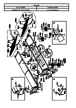
Страница 44: ...PEDANE PLATFORMS FAHRSCHIENE CHEMINS DE ROULEMENT PLATAFORMAS...
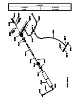
Страница 45: ...CILINDRO CYLINDER ZYLINDER V RIN CILINDRO...
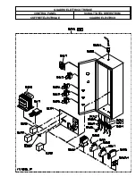
Страница 47: ...QUADRO ELETTRICO TRIFASE CONTROL PANEL SCHALTTAFEL DREHSTROM COFFRET LECTRIQUE CUADRO ELECTRICO...

