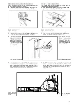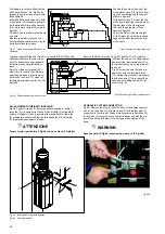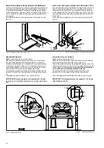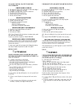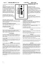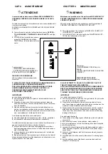
MONTAGGIO RAMPE DI SALITA E ARRESTI FERMARUOTA
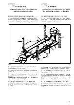
Le rampe di salita (pos.41, Fig.56) e gli arresti fermaruota (42) pos-
sono essere montati da ambo le parti delle pedane (7-8) secondo
le necessità dell’utilizzatore. Procedere al montaggio incastrando
sul lato desiderato le rampe di salita (41) e fissare tramite viti (43 e
48), le rosette (44) e i dadi (45 e 49) gli arresti fermaruota (42) sul
lato opposto.
Se richiesto montare le viti di regolazione per la posizione a terra
(50 e 51).
Fig.56
Fissaggio rampe e bloccaggi ruote
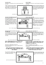
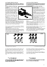
REGISTRAZIONE FUNI
Fig.57
: salire sul ponte con un’autovettura.
Posizionarsi all’altezza massima e verificare che i 4 martel-letti
(32) siano alloggiati dentro le asole delle aste di sicurezza (12).
Verificare che la distanza tra i martelletti (32) e le asole delle aste
di sicurezza (12) sulle 4 colonne (1-2-3-4) sia 20mm minimo dal
suo appoggio (
fig.57
) una misura inferiore non darebbe il tempo
alla sicurezza ri ruotare rimanendo agganciata all’asta.
Se necessario procedere al livellamento agendo sui dadi (20) dei
terminali (19) delle funi (33)e regolando il microinterruttore finecor-
sa.
A registrazione ultimata bloccare con i controdadi (35).
IMPORTANTE: Questa operazione di registrazione é da ripe-
ter-si dopo 1 o 2 settimane dalla messa in servizio del solleva-
tore.
Fig.57
Registrazione funi
INSTALLING THE VEHICLE RAMPS AND THE WHEEL STOPS
The vehicle ramps (pos.41, fig.56) and the wheel stops (42) can be
fitted on either end of platforms (7 - 8) according to the user’s re-
quirements. Fit the ramps (41) by slotting them into the platforms
on the required end and then fix the wheel stops (42) on the oppo-
site end using screws (43 and 48), the washers (44), and the nuts
(45 and 49).
If requered fit the regulation screws for ground positionament (50
and 51).
Fig.56
Securing the vehicle ramps and wheel stops
ADJUSTING THE LIFT CABLES
Fig.57
: drive a vehicle onto the lift.
Raise the lift to the maximum height and check if the four wedges
(32) are fitted inside the slots of the safety rods (12).
Check if the distance between the wedges (32) and the slots of the
safety rods (12) on the 4 posts (1-2-3-4) is at least 20 mm from the
support (
fig. 57); a lower value would not allow the safety devi-
ce to rotate, and it would stay attached to the rod.
If necessary, level the unit by adjusting the nuts (20) on the
terminals (19) of the cables (33) and the limit micro switch.
When the adjustment is completed, lock with the lock nuts (35).
IMPORTANT: This adjustment must be repeated 1 or 2 weeks
after setting up the lift.
Fig.57
Adjusting the lift cables
32
12
32
20
35
19
33
41
47
46
51
43
44
44
42
45
50
48
49
Содержание 528C
Страница 1: ...I PONTE SOLLEVATORE A 4 COLONNE GB 4 POST LIFT 528C...
Страница 2: ......
Страница 13: ...SCHEMI ELETTRICI ED OLEODINAMICI WIRING DIAGRAMS AND HYDRAULIC 11...
Страница 28: ...Fig 40 Fig 40 26 B K X K X Fune K Colonne 1 3 Fune X Colonne 2 4 Cable K Posts 1 3 Cable X Posts 2 4...
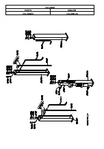
Страница 42: ...COLONNE POSTS S ULEN COLONNES COLUMNAS...
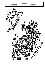
Страница 43: ...TRAVERSE CROSSBEAMS TRAVERSE TRAVERSES TRAVERSA OS...
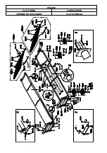
Страница 44: ...PEDANE PLATFORMS FAHRSCHIENE CHEMINS DE ROULEMENT PLATAFORMAS...
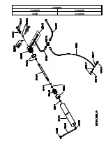
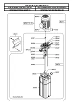
Страница 45: ...CILINDRO CYLINDER ZYLINDER V RIN CILINDRO...
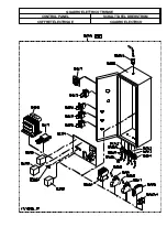
Страница 47: ...QUADRO ELETTRICO TRIFASE CONTROL PANEL SCHALTTAFEL DREHSTROM COFFRET LECTRIQUE CUADRO ELECTRICO...

