FISSAGGIO AL SUOLO DELLE COLONNE
Far scendere la piattaforma (vedere istruzioni d’uso) fino a circa 30
cm. da terra.
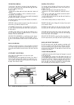
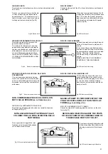
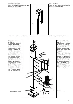
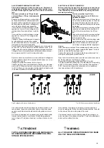
Posizionare le colonne in modo tale che i pattini in nylon (posterio-
re 37 e laterale 38) siano a contatto con le colonne (Fig.53).
Effettuare la messa a piombo delle colonne spessorando dove ne-
cessario le piastre di base.
L’operazione di spessoramento deve essere la più ampia pos-
sibile e sempre in prossimità dei fori di fissaggio.
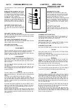
Premere il pulsante di salita (SB1
in Fig.50) ed effettuare una corsa
completa; durante tale corsa é
bene controllare (se necessario
fermandosi ogni 20-30 cm.) che lo
scorrimento delle traverse avven-
ga regolarmente senza anomali
sfregamenti.
Se durante questa operazione si
verificano mal funzionamenti é ne-
cessario rivedere la messa a
piombo delle colonne.
Fig.53 Regolazione pattini
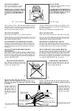
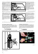
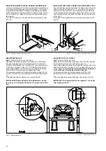
Al termine della salita controllare il cor-
retto funzionamento del finecorsa salita
(pos.39, Fig.54) e se necessario effet-
tuare la registrazione tramite la camma
(40) posta sulla traversa.
Fig.54
Fare scendere la piattaforma arrestan-
dosi a circa 30 cm. dal suolo,procedere
quindi alla foratura del pavimento attra-
verso i fori delle piastre di base delle
colonne.
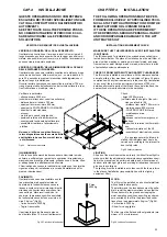
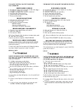
Per il fissaggio usare tasselli Ø16mm.,
M 10, lunghi 65mm., tipo FISCHER
SLM 10 o HILTI HB M10.
Serrare le viti con chiave dinamometri-
ca tarata a 35 Nm.
Fig.55 Fissaggio delle colonne
SECURING THE POSTS TO THE GROUND
Lower the platform (see operating instructions) until it is about 30
cm from the ground.
Position the posts so that the nylon shoes (rear 37 and side 38)
are in contact with the posts (fig.53.
Plumb the posts to ensure that they are perfectly perpendicular to
the floor, inserting shims where necessary under the baseplates.
Use shims that are as large as possible and always install
them close to the anchor holes.
Press LIFT button (SB1 in fig.50)
and complete the lift cycle; during
the cycle check that the cross-pie-
ces slide freely and without undue
rubbing friction (you may want to
stop the lift motion every 20 or 30
cm to make this inspection ea-
sier).
If you notice any malfunctions du-
ring this operation, check that the
posts are perfectly perpendicular.
Fig.53 Shoe adjustment
When the lift cycle is completed, make
sure that the lifting limit switch (pos.39,
fig.54) is working properly and if ne-
cessary, adjust using the cam (40) on
the cross-piece.
Fig.54
Lower the platform until it is about 30
cm from the ground and then drill into
the floor through the fixing holes in the
base plates.
Use screw anchors size Ø 16 mm, M
10, length 65 mm, type FISCHER
SLM 10 or HILTI HB M10.
Tighten the screws with a torque
wrench set to 35 Nm.
Fig.55 Post anchoring
31
36
37
39
40
Содержание 528C
Страница 1: ...I PONTE SOLLEVATORE A 4 COLONNE GB 4 POST LIFT 528C...
Страница 2: ......
Страница 13: ...SCHEMI ELETTRICI ED OLEODINAMICI WIRING DIAGRAMS AND HYDRAULIC 11...
Страница 28: ...Fig 40 Fig 40 26 B K X K X Fune K Colonne 1 3 Fune X Colonne 2 4 Cable K Posts 1 3 Cable X Posts 2 4...
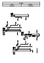
Страница 42: ...COLONNE POSTS S ULEN COLONNES COLUMNAS...
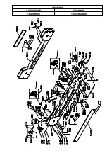
Страница 43: ...TRAVERSE CROSSBEAMS TRAVERSE TRAVERSES TRAVERSA OS...
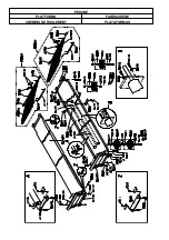
Страница 44: ...PEDANE PLATFORMS FAHRSCHIENE CHEMINS DE ROULEMENT PLATAFORMAS...
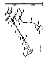
Страница 45: ...CILINDRO CYLINDER ZYLINDER V RIN CILINDRO...
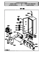
Страница 47: ...QUADRO ELETTRICO TRIFASE CONTROL PANEL SCHALTTAFEL DREHSTROM COFFRET LECTRIQUE CUADRO ELECTRICO...

