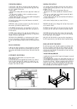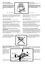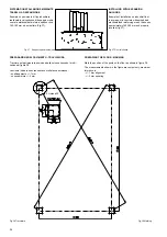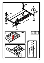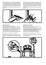
Posizionare le colonne all’estremità
delle traverse (pos. 5-6, Fig.39) se-
guendo la numerazione e lo schema
della figura 39.
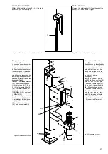
Infilare dall’alto delle colonne le aste
di sicurezza (12) facendole passare
tra la parte posteriore delle traverse
(5-6) ed i perni di guida (13) come in
figura 43.
Verificare che le aste di sicurezza sia-
no diritte.
Montare le aste di sicurezza con i
bordi arrotondati delle asole verso la
parte frontale delle colonne.
Fig.43
Sede di inserimento dell’asta di
sicurezza
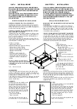
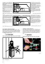
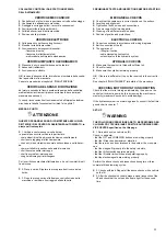
Togliere i dadi M20 (pos.25, Fig.42) e le rosette Ø21x37(26) dall’e-
stremità delle funi e inserire i termi-
nali (19) delle stesse negli appositi
fori delle piastre superiori delle co-
lonne.
Fig.42: avvitare sui terminali (19) i
dadi (25) e le rosette (26). Durante
questa operazione é importante ve-
rificare che i sensori (17) siano cor-
rettamente posizionati sulle funi (18)
figura 45.
Fig.45
Posizionamento dei sensori fune
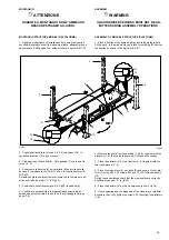
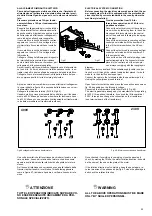
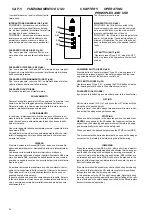
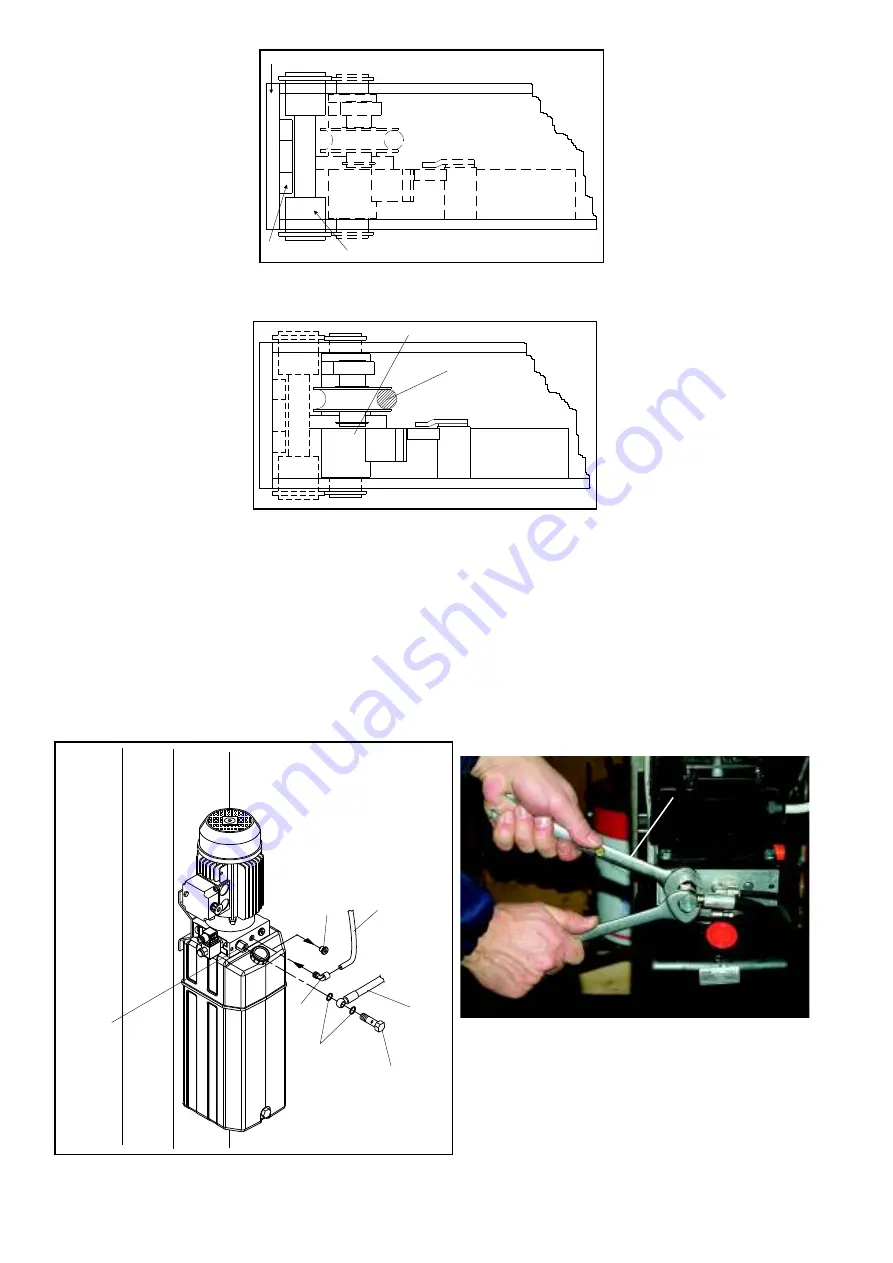
ALLACCIAMENTO IMPIANTO IDRAULICO
Fig.46: Togliere il tappo (1) dal corpo della centralina, avvitare il
raccordo (2) e inserire nello stesso il tubo di sfiato (3) collegato al
cilindro. Collegare il tubo in gomma alta pressione (4) al raccordo
(5) premontato sulla centralina con le rondelle (6) e la vite forata
(7) in dotazione serrandolo a fondo.
I
ATTENZIONE
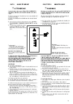
Tenere fermo il particolare 5 Fig.46 con una chiave (6 Fig.46a).
Fig.46
Allacciamento impianto idraulico
Fig.46
Hydraulic system
Position the posts at the end of the
cross-pieces (pos. 5-6, fig.39) obser-
ving the numbering and the lay-out
shown in figure 39.
Fit the safety rods (12) from the top
of the posts, inserting them between
the rear face of the cross-pieces
(5-6) and the guide pins (13) as
shown in figure 43.
Check the Safety rods are straight.
Fit the Safety rods with the rounded
edges of the slots towards the front
of the posts.
Fig.43 Housing for fitting safety rod
Remove the M20 nuts (pos.25, fig.42) and the 21 x 37 washers
(26) from the ends of the lifting cables
and install the terminal blocks (19) in
the relevant holes on the top plates of
the posts.
Fig. 42: screw the nuts (25) and wa-
shers (26) onto the terminal blocks
(19). During this procedure make sure
that the sensors (17) are correctly po-
sitioned on the lifting cables (18) as
shown in fig. 45.
Fig.45 Positioning of lifting cable sensors
HYDRAULIC SYSTEM CONNECTION
Fig.46: Remove the plug (1) from the body of the hydraulic power
unit, screw the union (2) in its place, and fit the breather pipe (3)
connected to the cylinder. Connect high pressure rubber hose (4)
to the union (5) mounted on the hydraulic power unit with the wa-
shers (6) and the drill srew (7) to equipment and tighten it fully
down.
I
WARNING
Keep the detail 5 Fig.46 locked using a wrench (6 Fig.46a).
Fig.46a
28
1
3
7
4
6
5
2
6
12
13
5-6
14
18
Содержание 528C
Страница 1: ...I PONTE SOLLEVATORE A 4 COLONNE GB 4 POST LIFT 528C...
Страница 2: ......
Страница 13: ...SCHEMI ELETTRICI ED OLEODINAMICI WIRING DIAGRAMS AND HYDRAULIC 11...
Страница 28: ...Fig 40 Fig 40 26 B K X K X Fune K Colonne 1 3 Fune X Colonne 2 4 Cable K Posts 1 3 Cable X Posts 2 4...
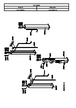
Страница 42: ...COLONNE POSTS S ULEN COLONNES COLUMNAS...
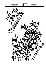
Страница 43: ...TRAVERSE CROSSBEAMS TRAVERSE TRAVERSES TRAVERSA OS...
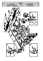
Страница 44: ...PEDANE PLATFORMS FAHRSCHIENE CHEMINS DE ROULEMENT PLATAFORMAS...
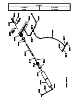
Страница 45: ...CILINDRO CYLINDER ZYLINDER V RIN CILINDRO...
Страница 47: ...QUADRO ELETTRICO TRIFASE CONTROL PANEL SCHALTTAFEL DREHSTROM COFFRET LECTRIQUE CUADRO ELECTRICO...

