COLLAUDI E CONTROLLI DA EFFETTUARE PRIMA
DELL’AVVIAMENTO
VERIFICHE MECCANICHE
·
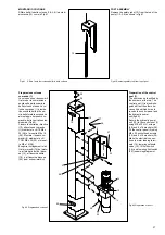
Controllare che le funi siano in posizione corretta sulle pulegge;
·
Livellamento e allineamento macchina;
·
Fissaggio e serraggio bulloni, raccordi e connessioni;
·
Scorrimento libero delle parti mobili;
·
Pulizia delle varie parti della macchina;
·
Posizione delle protezioni.
VERIFICHE ELETTRICHE
·
Collegamenti corretti secondo gli schemi;
·
Messa a terra della macchina;
·
Funzionamento dei seguenti dispositivi:
- finecorsa di salita,
- finecorsa di allentamento funi.
- elettrovalvola dell’impianto oleodinamico.
VERIFICA IMPIANTO OLEODINAMICO
·
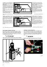
Presenza d’olio in quantità idonea nel serbatoio;
·
Assenza di trafilamenti;
·
Funzionamento cilindro.
N.B. In caso d’assenza d’olio, immettere nel serbatoio della centra-
lina la quantità di olio mancante.
Vedere la procedura nel capitolo 6: “MANUTENZIONE”.
VERIFICA DEL SENSO DI ROTAZIONE
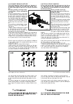
del motore secondo la freccia posta sulla pompa della centralina,
mediante brevi avviamenti (ciascun avviamento deve durare al
massimo due secondi).
In caso di inconvenienti nel funzionamento dell’impianto oleodina-
mico vedere tabella “inconvenienti e rimedi” al capitolo 7.
MESSA A PUNTO
I
ATTENZIONE
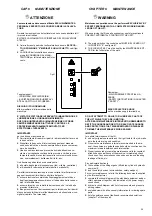
QUESTE OPERAZIONI SONO DI COMPETENZA ESCLUSIVA
DEI TECNICI DEL CENTRO DI ASSISTENZA AUTORIZZATO, in-
dicato nel frontespizio .
·
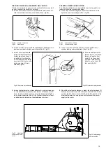
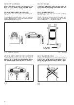
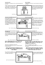
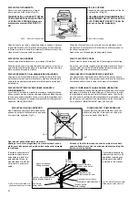
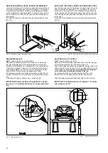
1.Verifica a vuoto (senza veicoli a bordo)
In questa fase occorre verificare in particolare:
- che i pulsanti di salita e discesa funzionino correttamente
- che il ponte raggiunga l’altezza massima;
- che non vi siano vibrazioni anomale nelle colonne e nelle traver-
se;
- che i martelletti si innestino nelle aste di sicurezza;
- che il finecorsa salita intervenga;
- che i finecorsa funi intervengano
- che gli elettromagneti intervengano
Per le verifiche sopracitate effettuare due o tre cicli completi di sali-
ta e discesa.
·
2. Prove a carico. Ripetere le prove precedenti con veicolo a
bordo.
·
3. Dopo le prove a carico effettuare un controllo visivo della
macchina e riverificare il serraggio della bulloneria.
PRELIMINARY TESTS AND INSPECTIONS BEFORE STARTING
MECHANICAL CHECKS
·
Check that the cables are in correct position on the pulleys;
·
Levelling and alignment;
·
Tightness of bolts, unions and connections;
·
Free movement of all moving parts;
·
Cleaning of the different machine parts;
·
Position of guards and protections.
ELECTRICAL CHECKS
·
Correct connections in accordance with wiring diagrams;
·
Earth connection of the lift;
·
The operation of:
- lifting limit switch,
- cable slackening limit switch,
- solenoid valve in the hydraulic system.
HYDRAULIC CHECKS
·
Make sure the reservoir is filled with sufficient oil;
·
Check for leaks;
·
Make sure the cylinder is working properly.
N.B. If there is insufficient oil, top up the reservoir to the correct le-
vel.
See chapter 6 “MAINTENANCE” for details of the procedure.
CHECKING MOTOR ROTATION DIRECTION
Check that the motor is turning as indicated by the arrow on the
control unit hydraulic pump; do this by running the machine mo-
mentarily (maximum 2 seconds to avoid damage).
If the hydraulic system is not working properly, consult the fault dia-
gnosis chart in chapter 7.
SET-UP
I
WARNING
THE FOLLOWING OPERATIONS ARE TO BE PERFORMED EX-
CLUSIVELY BY TECHNICIANS FROM THE AUTHORISED SER-
VICE CENTRE specified on the title page.
·
1.No-load check (no vehicle on lift)
Check, in particular:
- that the LIFT and LOWERING buttons are working properly
- that the lift reaches its maximum elevation;
- that there are no undue vibrations in the posts or the cross-pie-
ces;
- that the wedges fit properly into the safety rod slots;
- that the lift limit switch operates properly;
- that the lift cable limit switches are operating properly;
- that the electromagnets are working properly.
Perform the above checks and inspections during two or three
complete lift and lowering cycles.
·
2. Checks with load. Repeat all the above checks with a vehicle
on the lift.
·
3. After the checks with vehicle make a visual inspection of the
lift and check that the nuts and bolts are tight for the second
time.
33
Содержание 528C
Страница 1: ...I PONTE SOLLEVATORE A 4 COLONNE GB 4 POST LIFT 528C...
Страница 2: ......
Страница 13: ...SCHEMI ELETTRICI ED OLEODINAMICI WIRING DIAGRAMS AND HYDRAULIC 11...
Страница 28: ...Fig 40 Fig 40 26 B K X K X Fune K Colonne 1 3 Fune X Colonne 2 4 Cable K Posts 1 3 Cable X Posts 2 4...
Страница 42: ...COLONNE POSTS S ULEN COLONNES COLUMNAS...
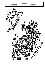
Страница 43: ...TRAVERSE CROSSBEAMS TRAVERSE TRAVERSES TRAVERSA OS...
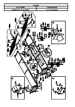
Страница 44: ...PEDANE PLATFORMS FAHRSCHIENE CHEMINS DE ROULEMENT PLATAFORMAS...
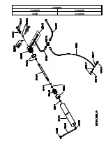
Страница 45: ...CILINDRO CYLINDER ZYLINDER V RIN CILINDRO...
Страница 47: ...QUADRO ELETTRICO TRIFASE CONTROL PANEL SCHALTTAFEL DREHSTROM COFFRET LECTRIQUE CUADRO ELECTRICO...

