68
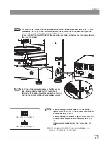
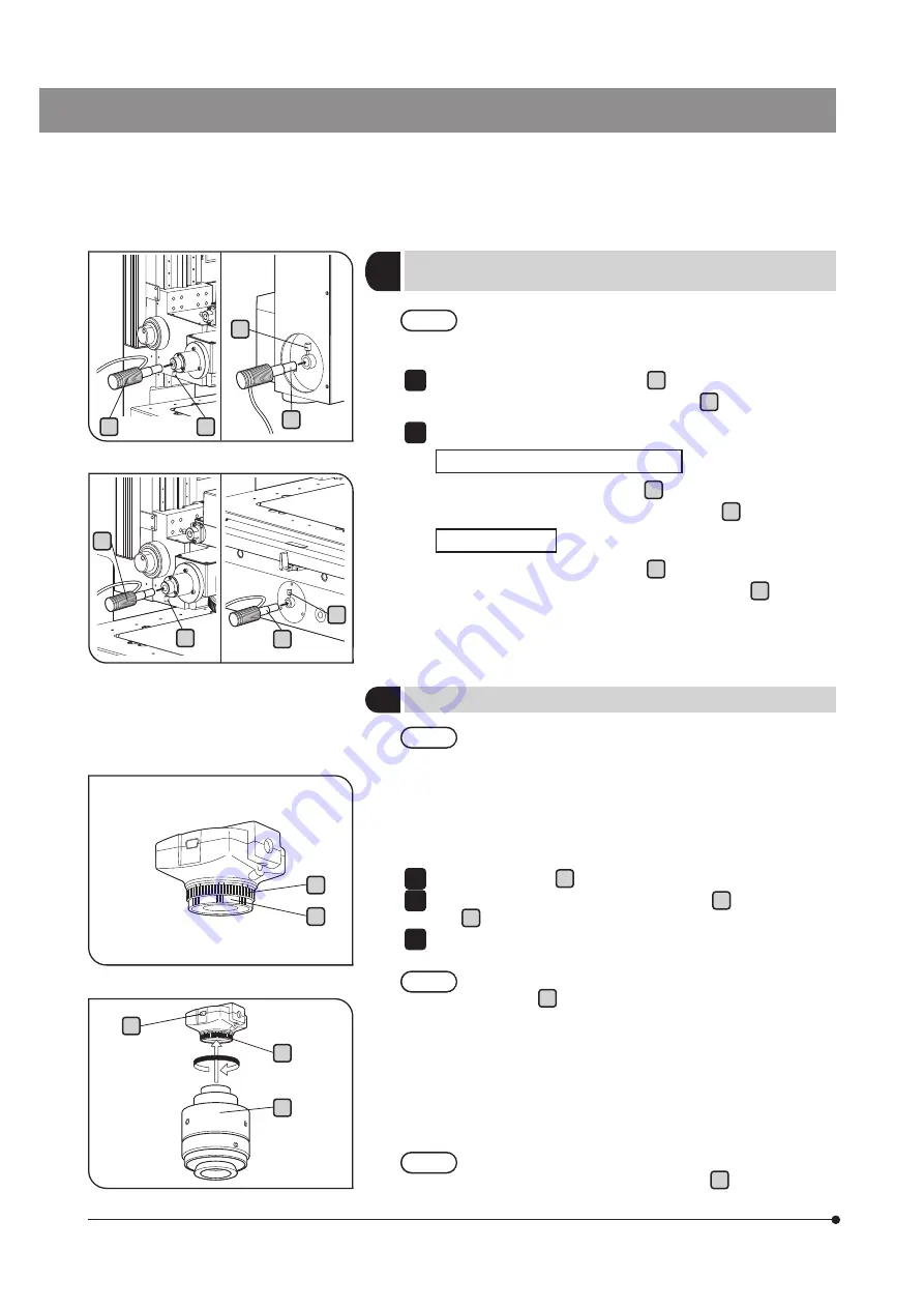
Insert the white LED unit (MM6-ILW) a into the port on the reflected
light unit and clamp with the clamping knob b .
Insert the green LED unit (MM6-ILG) into the frame.
STM7-SF/STM7-SFA/STM7-MF/STM7-MFA
Insert the green LED unit (MM6-ILG) c into the lower part on the rear
of the frame, and clamp with the clamping knob d .
STM7-LF/STM7-LFA
Insert the green LED unit (MM6-ILG) c into the lower part on the left
side of the frame, and clamp with the clamping knob d .
1
2
Cables and cords are vulnerable when bent or twisted.
Never subject them to excessive force.
CAUTION
13
Connecting the LED light to the output end
(MM6-ILW, MM6-ILG)
14
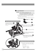
Mounting the digital camera
·
The camera head and camera adapter are precision
modules.
Be careful not to drop them during attaching or detaching.
·
Keep the dust cap in a safe place. It will be used for next
transportation.
} The following procedure deals with the case using the U-TV1XC
C-mount camera adapter.
Rotate the dust cap e of the camera to remove.
Screw in the U-TV1XC C-mount camera adapter f into the extension
ring g at the bottom of the camera head.
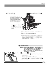
Attach the C-mount camera adapter to the camera port of the
microscope.
Attach the camera adapter to the camera port so that the
connector
h
of the digital camera comes to the right
side.
} If the camera is attached in a wrong direction, the direction of the
image observed through the eyepiece does not match with the
direction of the image through the camera.
After the camera is installed, compare the image observed through
the eyepiece to the live image acquired by the camera, and rotate
the camera adapter to match these images.
For details, refer to "7-1 Adjusting the tilt of the camera" (page 81).
When removing the camera from the camera adapter, be
careful not to allow the extension ring
g
removed from
the camera.
CAUTION
1
2
3
CAUTION
CAUTION
g
g
e
f
STM7-LF/STM7-LFA
a
b
c
d
a
b
c
d
STM7-SF/STM7-SFA/STM7-MF/STM7-MFA
h


