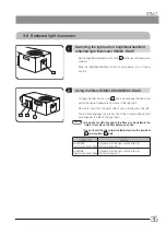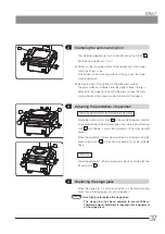
ON
OFF
1 2 3 4 5 6 7 8
SW1
SW2
SW3
1 2 3 4 5 6 7 8
G 1
2
3
4
5
67
89
A
B
C
D
E
F
49
STM7
55
MEASUREMENT
5-1 Preparation (setting DIP switch and rotary switch)
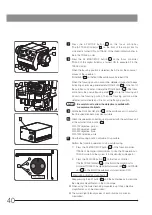
} Following settings are available by the DIP switch of the control box STM7-CB/STM7-CBA.
1) Unit (μm/mm/inch/mil)
2) Minimum digit
3) Buzzer
4) Restoration of light intensity value at startup
5) Enable/disable of LED control for focus navigator unit
6) Whether or not to transmit the counter data
7) Enable/disable of interlock between coded revolving nosepiece and illumination
8) Output of counter data when using the autofocus unit
9) Origin search at startup
10) Microscope information display time
11) Axis to transmit the counter data
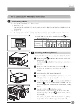
} Be sure to set the DIP switch when the main switch of the control box is " " (OFF).
When the main switch is set to " " (ON), the setting of the DIP switch is loaded to the microscope.
·
Be careful not to touch the internal circuit boards when setting the DIP switches. If a circuit board is
contacted, it may be destroyed by the static electricity.
·
Since a human body is charged with a small amount of static electricity, it should be discharged from
your body before proceeding to setting. The static electricity in your body can be discharged by simply
touching any metallic object.
CAUTION
b
Set the main switch a on the rear of the control box STM7-CB/STM7-
CBA to " " (OFF).
1
Take off the seal b on the front of the control box.
2
Set the DIP switches by using a flat-blade screwdriver.
3
a


