background image

X

Y

Z

DATA

Z LIMIT

COUNT

FULL

HALF

TRACK

SHOT

COARSE

EPI

DIA

FN

FINE

AF

FOCUS

LED

29

STM7

3


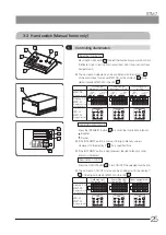
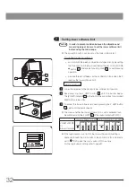
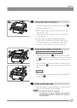
Controlling illumination

Selecting illumination

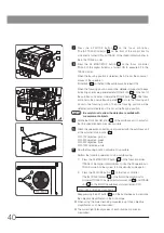
Press the SEL button  a  to select the illumination you want to control. 
(Reflected light illumination/transmitted light illumination/focus 
navigator unit)


} The illumination selected can be confirmed by the indicator  b  of 

the control box for motorized STM7-CBA or the display X  c  of the 
digital indicator STM7-DI or the LED  j .

Reflected light 

illumination: selected

Transmitted light 

illumination: selected

Focus navigator unit: 

selected

STM7-CBA 

(Always displayed)

MCZ

F  FINE

F  COARSE

MCZ

F  FINE

F  COARSE

MCZ

F  FINE

F  COARSE

Display X of 
STM7-DI

(Displayed for a 
specified time)

X

Y

Z

X

Y

Z

X

Y

Z

LED of 
STM7-DI

(Always displayed)

Z LIMIT

COUNT

FULL

HALF

TRACK

SHOT

COARSE

EPI

DIA

FN

FINE

AF

FOCUS

LED

Z LIMIT

COUNT

FULL

HALF

TRACK

SHOT

COARSE

EPI

DIA

FN

FINE

AF

FOCUS

LED

Z LIMIT

COUNT

FULL

HALF

TRACK

SHOT

COARSE

EPI

DIA

FN

FINE

AF

FOCUS

LED

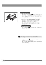
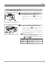
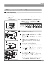
Controlling light intensity

Press the INTENSITY button  f  to control the illumination intensity. 

: Brighter 
: Darker


} If the INTENSITY button is pressed, the light intensity value is 

displayed on the display Z  e  for a specified time.


} If the INTENSITY button is kept pressed, the light intensity control 

interval is increased.

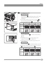
Illumination ON/OFF

Press the ON/OFF button  g  to turn ON/OFF the selected illumination.


} The illumination ON/OFF status can be confirmed with the display Y 

d  of the digital indicator STM7-DI or the LED  j .

Reflected light 

illumination: ON

Transmitted light 

illumination: ON

Focus navigator unit: 

ON

Display Y of 
STM7-DI

(Displayed for a 
specified time)

X

Y

Z

X

Y

Z

X

Y

Z

LED of 
STM7-DI

(Always displayed)

Z LIMIT

COUNT

FULL

HALF

TRACK

SHOT

COARSE

EPI

DIA

FN

FINE

AF

FOCUS

LED

Z LIMIT

COUNT

FULL

HALF

TRACK

SHOT

COARSE

EPI

DIA

FN

FINE

AF

FOCUS

LED

Z LIMIT

COUNT

FULL

HALF

TRACK

SHOT

COARSE

EPI

DIA

FN

FINE

AF

FOCUS

LED

b

a

g

h

i

f

c

d
e

j

Содержание STM7

Страница 1: ...se of this microscope we recommend that you study this manual thoroughly before operating the microscope Retain this instruction manual in an easily accessible place near the work desk for future refe...

Страница 2: ...uses and can radiate radio frequency energy and if not installed and used in accordance with the instruction manual may cause harmful interference to radio communications Operation of this product in...

Страница 3: ...and Z axis 26 3 Outputting counter data of X Y and Z axis 27 4 Counting counter data of X Y and Z axis in half 27 3 4 Focus controller Motorized frame only 28 1 Z axis coarse focusing 28 2 Z axisfine...

Страница 4: ...of focus 38 3 9 Autofocus unit Motorized frame only 39 1 Autofocusing modes 39 2 Focusing position adjustment 39 3 Measurement by manual readout in ONE SHOT mode 41 4 Measurement by auto readout in ON...

Страница 5: ...4 5 3 Measurement of height motorized frame only 54 5 4 Measurement of cylinders round rods and screws 55 6 ASSEMBLY 56 6 1 Assembly Diagram 56 6 2 Detailed assembly procedures 57 6 3 Inputting settin...

Страница 6: ......

Страница 7: ...nual type frame In this instruction manual the Z axis manual type frames STM7 SF STM7 MF STM7 LF are called Manual frame and the Z axis motorized type frames STM7 SFA STM7 MFA STM7 LFA are called Moto...

Страница 8: ...using devices and make sure that the control box is not operated excessively CAUTION Installation of the device Always use the power cord provided by Olympus If the proper power cord is not used the e...

Страница 9: ...ot touch around the opening of the Z axis motorized type Your hands or fingers may be pinched CAUTION Protection for injury Do not look directly at the light coming out from the objective lens and the...

Страница 10: ...ns Positions of caution labels Upper area of the stage X axis knob Upper area and lower area of the motorized frame STM7 SFA STM7 MFA STM7 LFA Z axis guide Lower area of both sides of the column of th...

Страница 11: ...cted to large vibrations or change in temperature 3 Near equipment producing abnormal noise including non Olympus equipment 4 In a place subjected to direct sunlight 5 In a place subjected to excessiv...

Страница 12: ...ge STM7 CS200 STM7 CS300 using the transport sticks Weight of each unit 59 8 kg STM7 CS200 111 3 kg STM7 CS300 Weight applied on one transport stick Approx 15 kg STM7 CS200 Approx 27 8 kg STM7 CS300 7...

Страница 13: ...the emergency stop switch 2 To release the switch rotate the emergency stop switch in the resetting direction clockwise and then rotate the fine coarse focusing knob of the focus controller STM7 MCZ...

Страница 14: ...0 comes out below the stage mounting surface When placing the stage on the table etc avoid the Y axis knob from contacting the table surface 2 When you purchase a new stage or replace repair the stage...

Страница 15: ...is used with connecting to the network the data import may fail or the system could not be operated properly due to the automatic update of the operating system etc Disable the automatic update of the...

Страница 16: ...cannot be used Rotatable stage 1 Do not attach the rotatable stage on the stage by reversing front and back right and left and up and down 2 Use the fine focusing knob lower right area of the stage t...

Страница 17: ...ure to use the dedicated transporting tools and packing materials Consult your local Olympus representative for details 4 When transporting be sure to use the Z axis transport lock and clamps screws E...

Страница 18: ...clean them use a lint free soft cloth slightly moistened with a diluted neutral detergent 3 When cleaning the base unit of the frame use the cleaner dedicated to the stone surface plate 4 After use r...

Страница 19: ...iece Coded revolving nosepiece U 5RE U D6RE U 5BDRE U D5BDRE U 5RES ESD U D5BDRES ESD Objectives MM6 OB1X MM6 OB5X MM6 OB10X MM6 OB3X 2 UIS2 UIS objective series Used together with the BD M AD adapter...

Страница 20: ...information on the modules marked with refer to their instruction manuals Either the focus navigator unit STM7 FN or the autofocus unit STM7 AF can be combined with the motorized frame Frame STM7 SFA...

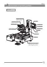
Страница 21: ...ight path selector knob Observation light path Photo TV light path Interpupillary distance scale Frame STM7 SF small manual frame STM7 MF middle manual frame STM7 LF large manual frame Stage glass Foc...

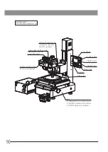
Страница 22: ...frame STM7 LFA large manual frame Stage glass DATA button Z RESET button Y RESET button X RESET button X Y Z display Motorized frame STM7 SFA STM7 MFA STM7 LFA Light path selector knob Observation li...

Страница 23: ...r X axis knob X axis clutch lever ON OFF button Z RESET button CALL button DATA HALF button SET button LED SEL button Reflected light illumination Transmitted light illumination Focus navigator unit M...

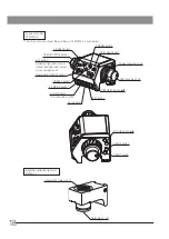
Страница 24: ...he autofocus unit STM7 AF is connected AF START STOP button Illumination ON OFF button Z RESET button AF MODE button AF OB button 10x 20x 50x 100x CALL button SEL button Reflected light illumination T...

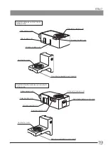
Страница 25: ...inator mount Filter insertion slot Polarizer insertion slot Observation tube mount Analyzer insertion slot Revolving nosepiece mount dovetail Fiber cable mount Filter insertion slot Polarizer insertio...

Страница 26: ...t installation block LED light emitter block Green LED unit Connector Main switch ON OFF Cross frame Brightness control Turn clockwise to increase the light intensity Transmitted light illumination Fo...

Страница 27: ...icator LEDs FINE ADJUST knob Used in fine adjustment of focusing position FOCUS LED Lights when focusing is obtained LASER LED Lights when AF is operated Dummy slider CBA connector Connection cable ST...

Страница 28: ...of the control box STM7 CB STM7 CBA to ON Only when using the control box Set the main switches of the modules you are using to ON For details refer to the instruction manual provided with each module...

Страница 29: ...motorized frame only movement distance of the fine coarse focusing knob motorized frame only illumination ON OFF and the illumination to be controlled Excel transfer tool When this software is instal...

Страница 30: ...he opposite direction to increase it If the focusing unit lowers by its own weight or the focus obtained with the fine focusing knob b is lost soon the tension is set too loose In this case turn the r...

Страница 31: ...EPI DIA FN FINE AF FOCUS LED Z LIMIT COUNT FULL HALF TRACK SHOT COARSE EPI DIA FN FINE AF FOCUS LED Controlling light intensity Press the INTENSITY button b to control the illumination intensity Brigh...

Страница 32: ...nsmitted light illumination focus navigator unit can be memorized When using the coded revolving nosepiece the light intensity values of up to five sets can be memorized according to the number of hol...

Страница 33: ...ed when the button is pressed is held in memory When keeping the DATA HALF button pressed further again the count in half function is turned OFF The value displayed at this time is also held in memory...

Страница 34: ...med by the indicator e of the control box for motorized STM7 CBA or the FOCUS f of the digital indicator STM7 DI Movement distance Small Movement distance Large Coarse focusing knob Fine focusing knob...

Страница 35: ...FULL HALF TRACK SHOT COARSE EPI DIA FN FINE AF FOCUS LED Z LIMIT COUNT FULL HALF TRACK SHOT COARSE EPI DIA FN FINE AF FOCUS LED Controlling light intensity Press the INTENSITY button f to control the...

Страница 36: ...unit When using the manual revolving nosepiece the light intensity values of one set reflected light illumination transmitted light illumination focus navigator unit can be memorized When using the co...

Страница 37: ...vement distance The value displayed when the button is pressed is held in memory When keeping the DATA HALF button pressed further again the count in half function is turned OFF The value displayed at...

Страница 38: ...software limit position Keep pressing the Z LIMIT button c until the buzzer beeps The Z LIMIT indicator d on the front of the control box for motorized STM7 CBA is turned ON To cancel the lower softw...

Страница 39: ...focusing unit or the fine coarse focusing knob f of the focus controller STM7 MCZ to bring the specimen on the stage into focus For details of the focus controller STM7 MCZ see 3 4 Focus controller M...

Страница 40: ...op in the cross a so that the side with indications faces downwards Attach the cross frame b again before observation Slide the light path selector knob c to select the desired light path Indication L...

Страница 41: ...on purpose in the light path Be sure to insert from the arrow side shown in the figure on the left The first click engages the idle position of the slider and the second click engages the filter in th...

Страница 42: ...rn slowly will fix the clutches And the stage can be moved by using the X and Y axis knobs e f If a clutch cannot be engaged try engaging the clutch again or turn the feed knob slightly and retry Do n...

Страница 43: ...he rotatable stage and jig tool can be attached using the tap a M4 threading depth max 7 mm Flatness of the mounting surface of the jig attached to the stage should be 40 m or less If the flatness of...

Страница 44: ...the diopter influence focusing repeatability Adjust surely Adjust the brightness of the reticle by using the light intensity control function of the hand switch STM7 HS the focus controller STM7 MCZ o...

Страница 45: ...manual provided with each module 1 2 Adjust the diopter of the eyepiece see page 33 Approximately focus on an apparently flat specimen such as a mirror or the glass surface of stage see page 28 3 4 b...

Страница 46: ...T knob l of the autofocus unit to adjust so that the specimen becomes clearly visible Attach the aberration correction seal provided with the autofocus unit at the adjusted knob position o With 10X ob...

Страница 47: ...r is turned ON When the focusing position is detected one short beep indicating the completion is generated FOCUS LED f on the front of the autofocus unit is turned ON and SHOT of the digital indicato...

Страница 48: ...icator is turned ON Whenthefocusingpositionisdetected ashortbeepindicatingcompletionis generatedandthecoordinatesareoutputtotheexternalcomputingdevice FOCUS LED f on the front of the autofocus unit is...

Страница 49: ...which you want to detect focusing to the center of crosslines of the eyepiece page 36 Press the AF START STOP button f on the focus controller TRACK of the digital indicator is turned ON to execute AF...

Страница 50: ...sing position is detected automatically and it tracks at the focusing position after the one short beep indicating the start of tracking is generated When you press the DATA HALF button j on the focus...

Страница 51: ...ected to FOOT SW connector of the control box STM7 CB STM7 CBA the counter data can be transmitted to the controller or the printer etc by pressing the foot switch 3 12 External processing device 3 13...

Страница 52: ...yzer insertion slot When using the U AN take care not to push it in past the click position Otherwise the U AN may get stuck in the back and be incapable of being removed When using the autofocus unit...

Страница 53: ...lor contrast Rotating the prism movement knob d on the DIC slider b varies the background interference color continuously from gray sensitive color to magenta sensitive color 100 to 600 nm Set the int...

Страница 54: ...roller STM7 MCZ to bring the specimen on the stage into focus Now the microscope is ready for simplified polarized light observation For details of the focus controller STM7 MCZ see 3 4 Focus controll...

Страница 55: ...formation display time 11 Axis to transmit the counter data Be sure to set the DIP switch when the main switch of the control box is OFF When the main switch is set to ON the setting of the DIP switch...

Страница 56: ...nsity value is not loaded The initial value of the factory default is loaded SW1 5 OFF The light intensity value is loaded ON Enable disable of focus navigator unit When selecting the illumination you...

Страница 57: ...n though the lower software limit is set during operation the setting value of the lower software limit is not saved if the main switch is set to OFF 4 When the lower software limit is set the setting...

Страница 58: ...etting information is displayed for two seconds SW2 4 OFF SW2 5 OFF The microscope setting information is displayed for three seconds ON OFF The microscope setting information is displayed for four se...

Страница 59: ...eyes forward backward and toward the left and right Assuming that the cross hairs are stationary if the image moves in the same direction as the eye movement bring the objective closer to the specime...

Страница 60: ...ersection of the eyepiece cross hairs and the counter coordinate readings should be X0 and Y0 Now press the X RESET and Y RESET buttons Next align the intersection of the cross hairs with points 1 2 a...

Страница 61: ...then bring the item into focus Align the horizontal eyepiece cross hair with the image of the generatrix by rotating the measured item or the rotatable stage and adjusting the Y axis knob Move the tab...

Страница 62: ...es which are not shown in the diagram please consult your Olympus representative or the latest brochures The assembly and adjustments are performed by the Olympus dealer As other tools than those prov...

Страница 63: ...Do not hold any part other than the transport sticks The microscope frame may be damaged If the installation table is dented by the legs of the frame due to the thin top board or if the microscope is...

Страница 64: ...screws b 2 pcs provided with the digital indicator by using the Allen screwdriver provided with the frame Hold the digital indicator until it is secured on the column 1 CAUTION a b c When using the d...

Страница 65: ...zed frame refer to 15 Connecting cable and cords page 69 and connect cables and cords Then set the main switch b of the control box for motorized STM7 CBA to ON and rotate the coarse focusing knob c o...

Страница 66: ...and wipe the attaching surface clean In STM7 CS50 or STM7 CS100 the Y axis knob is protruded below from the stage mounting surface Be careful not to allow the Y axis to touch the installation table P...

Страница 67: ...lamping screws when inserting them In case of STM7 CS200 or STM7 CS300 remove the transport sticks h 4 positions by rotating In case of STM7 CS50 or STM7 CS100 remove the transport rods i 2 positions...

Страница 68: ...on the left completely until it touches the bottom surface of the frame 1 2 CAUTION 4 Leveling the stage g h 5 Mounting the brightfield reflected light arm MM6C VL Fully loosen the clamp b stud of the...

Страница 69: ...the clamping screw h of the reflected light arm e using the Allen screwdriver provided with the frame 1 2 3 4 5 6 e f g h i 6 Mounting the reflected light illuminator MM6C KMAS MM6C RLAS 7 Mounting t...

Страница 70: ...eld series objective Screw in the objective conversion adapter BD M AD l into the objective mount j then mount the desired UIS2 UIS brightfield objective m on the BD M AD by screwing in firmly The UIS...

Страница 71: ...n the reflected light arm d using the Allen screwdriver provided with the microscope frame Turn the revolving nosepiece mount f 90 degrees Fix the revolving nosepiece mount by tightening the screws e...

Страница 72: ...the bottom of the observation tube h into the mount on the reflected light arm When using U TLU make the positioning reticle facing the front Tighten the tube clamping screw using the Allen screwdriv...

Страница 73: ...ar or a straight edge on the table approximately parallel with the table travel direction then adjust the positioning so that the intersection of the eyepiece cross hairs comes on the straight line of...

Страница 74: ...owing procedure deals with the case using the U TV1XC C mount camera adapter Rotate the dust cap e of the camera to remove Screw in the U TV1XC C mount camera adapter f into the extension ring g at th...

Страница 75: ...ame applies to other combinations If there are connection alternatives connect to the connector of the module you will use For connections of positions with mark contact Olympus for details CAUTION Po...

Страница 76: ...tuple revolving nosepiece When connecting DISPLAY of the control box with the digital indicator check the pin positions of the connector of the cable for digital indicator When connecting Z MOTOR of t...

Страница 77: ...xcess force is not applied to the foot of the round shape terminal or the bonding area of the round shape terminal and also they do not collide with other cables or cords CAUTION When connecting inter...

Страница 78: ...he cable a certain slack so that it does not hinder the vertical movement of the Z axis Secure the cables in the cable holder b giving the cable a certain slack so that it does not hinder the vertical...

Страница 79: ...s of X Y and Z axis unit of the counter display operations of X and Y axis knobs Z axis driving operations of the hand switch STM7 HS or the focus controller STM7 MCZ etc Before replacing the fuses se...

Страница 80: ...ON If you are using the control box for motorized STM7 CBA and also the origin search setting is ON the error sound beeps when the origin search is finished To input the setting values the values of X...

Страница 81: ...ode 1 b Setting the X axis counting direction While display X shows 1 press the Y RESET button d or the Z RESET button e to set the X axis counting direction in the display Y For setting values see 2...

Страница 82: ...he X RESET button c to show 6 in the display X 2 Press the DATA button f to change the digit you want to edit in the display Y 3 Press the Y RESET button d or the Z RESET button e to set the display Y...

Страница 83: ...or the Z RESET button e to set the Z axis counting direction in the display Y For setting values see 2 Setting Function List page 79 8 Inputting the standard value of Z axis 1 Press the X RESET button...

Страница 84: ...maker setting mode is closed and the microscope can be used in the normal status Without this procedure the inputted values are not saved in the microscope Be sure to execute this procedure 12 CAUTION...

Страница 85: ...front Positive Do not change unless necessary It is not necessary to set at delivery 1 Move the stage to back Positive 5 Standard value of Y axis 000 0001 to 999 9999 mm Value described in Certificat...

Страница 86: ...or the digital camera STM7 CU attach the camera adapter to the microscope so that the connector comes to the right side For the microscope digital camera DP22 DP27 attach the camera adapter to the mic...

Страница 87: ...l to the X axis 2 Look into the eyepiece with cross hairs with the right eye and move the stage so that the left end of the measurement object enters the field of view Then adjust the Y axis so that t...

Страница 88: ...lamping knob with the tool provided with the frame to fix the eyepiece with cross hairs 8 9 8 9 Slide the light path selector knob to move to the pulled out position The light path is 100 TV Photo 10...

Страница 89: ...FOCUS button AF START STOP button etc and fine coarse focusing knob Coarse movement speed 8 mm sec max Movement distance guide for per turn of fine coarse focusing knob can be selected from 4 values...

Страница 90: ...kg 17 7 kg 59 8 kg 111 3 kg Avoid subjecting the stage to excessively unbalanced load although the applied weight is within the accuracy assurance weight for it may impair the accuracy Do not place t...

Страница 91: ...on with adapter to mount measuring objectives STM7 MMOBAD UIS2 UIS brightfield metallurgical objectives Measurement objectives used in combination with adapter to mount measuring objectives STM7 MMOBA...

Страница 92: ...nce of the fine coarse focusing knob of the focus controller STM7 MCZ is small EPI green ON The reflected light illumination is turned ON OFF The reflected light illumination is turned OFF EPI orange...

Страница 93: ...ating system Microsoft Windows 7 Professional SP1 32bit 64bit Microsoft Windows 10 Pro Version 1511 1607 1703 1709 1803 1809 1903 1909 32bit 64bit Microsoft Windows 10 Pro for workstations Version 170...

Страница 94: ...FL10X 50X LMPLFL10X 50XBD UMPLFL10XBD2 MPL10X MPL10XBD MM6 OB10X Focusing repeatability 10X 3 5 m 20X 1 m 50X 0 7 m The experimental value by the mirror sample Applicable observation methods Reflected...

Страница 95: ...tion Temperature 10 C to 60 C Humidity 10 to 90 Conditions for safety standards Indoor use Altitude Max 2 000 meters Ambient temperature 5 to 40 C 41 to 104 F Maximum relative humidity 80 for temperat...

Страница 96: ...olving nosepiece is not set to a click position Set to a click position The filter is stopped at an intermediate position Set it properly 35 d Dirt or dust is observed in the field of view Dust or dir...

Страница 97: ...correct focusing is obtained The setting position of the lower software limit is wrong Set it correctly again 32 c The objective collides with the specimen even though the lower software limit is set...

Страница 98: ...perly 69 b The Excel transfer tool does not start Cables are not connected completely Connect them properly 69 The COM port is used for other functions Check the settings of the COM port again c The m...

Страница 99: ...error The counter data displayed after the error is canceled is not a correct value Perform the measurement again If you cannot solve the problem contact Olympus for assistance 69 o Display shows 013F...

Страница 100: ...ally the power supply cord which is approved by one of the agencies mentioned in Table 1 please use replacements approved by any other equivalent and authorized agencies in your country Country Agency...

Страница 101: ...ic Cables BASEC BASEC HAR 10 10 30 N V KEMA KEMA KEUR HAR 10 30 30 SEMKO AB Svenska Elektriska Materielkontrollanstalter SEMKO HAR 10 10 50 sterreichischer Verband f r Elektrotechnik VE VE HAR 30 10 5...

Страница 102: ...Memo...

Страница 103: ......

Страница 104: ...Distributed by Manufactured by Shinjuku Monolith 2 3 1 Nishi Shinjuku Shinjuku ku Tokyo 163 0914 Japan www olympus global com AX8428 11 Issued in January 2020...

Отзывы: