69
STM7
15
Connecting cable and cords
·
Cables and cords are vulnerable when bent or twisted.
Never subject them to excessive force.
·
Make sure that the main switches of the power supply
devices are set to “ ” (OFF) before connecting the power
cord.
·
Always use the power cords or functional ground cables
provided by Olympus. If no power cord is provided, please
select the proper power cord by referring to the section
“Proper selection of the power supply cord” at the end of
this instruction manual.
·
If the cable is equipped with the mounting screw, be sure
to tighten the mounting screw before using the system.
If you use the cable without tightening the mounting screw,
the malfunction or the failure is caused by the connection
failure of cables.
} The assembly procedures are illustrated in combination with the
middle motorized frame as a reference. Unless otherwise specified,
the same applies to other combinations.
} If there are connection alternatives, connect to the connector of the
module you will use.
} For connections of positions with * mark, contact Olympus for
details.
CAUTION
Power cord
Power cord
Hand switch
STM7-HS
Controller
Focus controller
STM7-MCZ
Foot switch
STM7-FS
DISPLAY of control box
ZLMT SNS of control box
To monitor
· Microscope digital
camera
· Digital camera
Monitor
To HS of control box
(manual frame only)
To FOOT SW of control box
To CAN1 or CAN2
of control box
(motorized frame only)
AF of control box (motorized frame only)
· Y SCALE of control box
· External processing device
· Z SCALE of control box
· External processing device
· X SCALE of control box
· External processing device
· DIA of control box
· Power supply unit MM6-ILPS-2
· EPI of control box
· Power supply unit MM6-ILPS-2
(When using the focus navigator unit)
· FN of control box
· Power supply unit MM6-ILPS-2
To controller
Z MOTOR of control box
(motorized frame only)
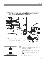
} Attach the ferrite core a provided with STM7-MCZ to the interface
cable (optional accessory).
70 mm
Connector of
STM7-MCZ
a


