


28
Chapter 3 Installation and Connection
VIDEO SYSTEM OTV-SI
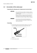
3.2
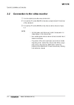
Connection to the video monitor
1.
Turn this instrument and the video monitor OFF.
2.
Connect the Y/C cable (MH-985) to the video output terminal (Y/C terminal)
of this instrument.
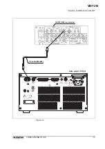
3.
Connect the Y/C cable (MH-985) to the video monitor as shown in Figure
•
Incorrect cable connections may result in inadequate or no
image display on the video monitor.
•
Non-medical grade video monitors must be connected via an
isolation transformer.
•
The position of the video input/output connectors is variable
depending on the model of the video monitor. When using a
video monitor other than the OEV143/203, confirm the
positions of the VIDEO and Y/C input connectors by referring
to its instruction manual.
VISY218
Содержание OTV-SI
Страница 2: ...VISY218...
Страница 6: ...Contents iv VIDEO SYSTEM OTV SI VISY218...
Страница 148: ...142 Chapter 7 Troubleshooting VIDEO SYSTEM OTV SI VISY218...
Страница 156: ...VISY218...
Страница 159: ...INSTRUCTIONS COMPACT TROLLEY TC C2 VISY218...
Страница 171: ...VISY218...
Страница 172: ...VISY218...
Страница 173: ...VISY218...