


100
Chapter 5 Operation
VIDEO SYSTEM OTV-SI
5.9
Remote control switches
This instrument’s functions can be assigned to the remote control switches on
the videoscope or camera head. The number of remote control switches
available depend on the videoscope or camera head being used (see Table 5.1).
Functions cannot be assigned to OTV-S7H-1D-F08E/L08E
/D-L08E.
Remote control switches can be assigned by navigating through the menu using
the remote control switches or the keyboard (optional).
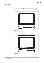
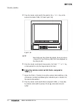
1.
If the video monitor does not display the menu, press the remote control
switch for execution or for selection, the “F1”, “Enter”, “
”, “
”, “
” or “
”
key on the keyboard to display the menu.
Restore default settings on the video system (see 5.14,
“Default settings”), or turn this instrument ON while pressing
both the “
” and “
” exposure level switches to reset the
function assignments of the remote control switches.
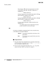
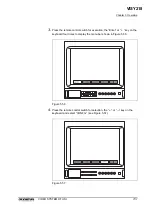
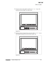
2.
Press the remote control switch for selection, the “
” or “
” key on the
keyboard and select “NEXT” (see Figure 5.6 on page 57).
The number of remote control switches
Videoscope/camera head models
4
ENF-V/V2/VQ, PEF-V,
CYF-V/VA, CYF-V2/VA2,
LF-V, HYF-V
2
OTV-S7H-N/1N/1D
0
OTV-S7H-1D-F08E/L08E/D-L08E
Table 5.1
VISY218
Содержание OTV-SI
Страница 2: ...VISY218...
Страница 6: ...Contents iv VIDEO SYSTEM OTV SI VISY218...
Страница 148: ...142 Chapter 7 Troubleshooting VIDEO SYSTEM OTV SI VISY218...
Страница 156: ...VISY218...
Страница 159: ...INSTRUCTIONS COMPACT TROLLEY TC C2 VISY218...
Страница 171: ...VISY218...
Страница 172: ...VISY218...
Страница 173: ...VISY218...