Olympus OTV-SI Скачать руководство пользователя страница 1

USA: CAUTION:

Federal law restricts this device to sale by or on the order of a physician.

INSTRUCTIONS

VIDEO SYSTEM

OTV-SI

VISY218

Содержание OTV-SI

Страница 1: ...USA CAUTION Federal law restricts this device to sale by or on the order of a physician INSTRUCTIONS VIDEO SYSTEM OTV SI VISY218...

Страница 2: ...VISY218...

Страница 3: ...Symbols and descriptions 12 2 2 Front panel 13 2 3 Rear panel 16 2 4 Side panel 18 2 5 Ancillary equipment 19 2 6 Keyboard optional 20 2 7 Menu actions 23 Chapter 3 Installation and Connection 25 3 1...

Страница 4: ...sic menu operation 54 5 3 Clock adjustment 57 5 4 Adjusting the video monitor 64 5 5 Color adjustment 67 5 6 Brightness adjustment 80 5 7 Image enhancement 91 5 8 Patient data entry deletion 93 5 9 Re...

Страница 5: ...I Chapter 7 Troubleshooting 138 7 1 Troubleshooting guide 138 7 2 Returning the instrument for repair 141 Appendix 143 System chart 143 Operating environment 146 Transportation and storage environment...

Страница 6: ...Contents iv VIDEO SYSTEM OTV SI VISY218...

Страница 7: ...ons shown below If labels or symbols are missing or illegible contact Olympus Rear side Potential equalization terminal Fuse rating label CSA marking Caution refer to instructions Caution refer to ins...

Страница 8: ...ls and Symbols VIDEO SYSTEM OTV SI Back cover of this instruction manual Manufacturer Authorized representative in the European Community Electrical rating label Fuse rating label Lamp rating plate VI...

Страница 9: ...effectively Before use thoroughly review this manual and the manuals of all equipment which will be used during the procedure and use the instruments as instructed Keep this and all related instructi...

Страница 10: ...pment damage Wash out The inability to see details in the endoscopic image due to excessive brightness Automatic brightness control Automatically adjusts the intensity of the light so that the endosco...

Страница 11: ...ot be resolved using the information in Chapter 7 contact Olympus Signal words The following signal words are used throughout this manual Indicates an imminently hazardous situation which if not avoid...

Страница 12: ...the operation of the equipment immediately and contact Olympus Do not prepare inspect or use this equipment with wet hands Never use this instrument in the presence of flammable substances or in an en...

Страница 13: ...proper illumination Do not prolong observation in close proximity to tissue or keep the distal end of the endoscope in contact with living tissue When discontinuing the use of the endoscope be sure t...

Страница 14: ...t and electrosurgery compatible endo therapy accessory when performing high frequency treatment Otherwise burns may result due to abnormal current flow The system should be establish with equipment co...

Страница 15: ...tion or seriously affect the cardiac function of the patient As specified by international standard IEC 60601 1 any Applied Part used for observation or treatment of the heart or areas near the heart...

Страница 16: ...ckage with the components shown below Inspect each item for damage If the instrument is damaged a component is missing or you have any questions do not use the instrument immediately contact Olympus T...

Страница 17: ...1 Checking the Package Contents 11 VIDEO SYSTEM OTV SI Type B Video system OTV SI SI spare fuse MAJ 1242 2 pcs Y C cable MH 985 BNC cable B MB 677 Power cord Instruction manual Water container MD 431...

Страница 18: ...l Rear panel Side panel Power ON Power OFF Video connector socket Connector for light guide plug Automatic control White balance Automatic manual Manual control Brightness Air feed Up Down Lamp Potent...

Страница 19: ...SI 2 2 Front panel Type A 1 Power switch 4 White balance switch 2 Video connector socket 3 Output connector 6 Manual indicator 5 Auto indicator 7 Auto Manual brightness selector 10 Unlocking lever 9 L...

Страница 20: ...4 White balance switch 2 Video connector socket 3 Output connector 6 Manual indicator 5 Auto indicator 7 Auto Manual brightness selector 10 Unlocking lever 9 Lamp selection lever 8 Brightness control...

Страница 21: ...selected 6 Manual indicator This indicator lights when the manual brightness control is selected 7 Auto Manual brightness selector This switch is pressed to select auto or manual brightness control 8...

Страница 22: ...2 3 Rear panel 1 Video output terminals Y C terminal 5 VTR remote terminal 2 Video output terminal BNC terminal 3 System terminal 6 Keyboard terminal 7 Fuse box 9 Potential equalization terminal 8 AC...

Страница 23: ...Communication signals for the color video printer OEP 3 OEP are transmitted via this terminal 5 VTR remote terminal The communication signals for the VTR are transmitted via this terminal 6 Keyboard t...

Страница 24: ...OTV SI 2 4 Side panel 1 Latch Pull up to open the lamp access cover 2 Water container holder type B only Hang the water container here 3 Lamp access cover Open to replace the lamp 2 Water container ho...

Страница 25: ...cable B MB 677 The cable connects this instrument with the color video monitor Power cord The cable connects this instrument with a wall mains outlet Water container MD 431 type B only The water cont...

Страница 26: ...lympus Use only the Olympus keyboard for OTV S7V MAJ 1124 1 Esc key 6 F5 key 2 F1 key 3 F2 key 7 F6 key 4 F3 key 5 F4 key 8 F7 key 9 F8 key 12 Enter key 11 Backspace key 10 F9 F12 keys 13 Delete key 1...

Страница 27: ...the menu for in which to input patient data 4 F3 key the freeze ON and OFF This key is pressed to turn the freeze ON and OFF the menu display for the freeze mode setup The F3 and the Shift key are pr...

Страница 28: ...monitor 14 keys These keys are pressed to display the menu bar if it is not displayed on the video monitor to execute the selected menu or to change the parameter in the brackets of some menus 15 keys...

Страница 29: ...e image enhancement level through 0 OFF 1 LOW 2 MEDIUM and 3 HIGH A normal size image is displayed on the video monitor A magnified image is displayed on the video monitor A normal non rotated image i...

Страница 30: ...e control switch assignments Select the FIELD mode of a freeze image Select the FRAME mode of a freeze image Save a remote control switch setting Display the hue adjusting menu Display the chroma adju...

Страница 31: ...horizontal to the terminal and push it in completely without applying excessive force If the connector is held at an angle or if excessive force is used to connect it the connector pins may be deform...

Страница 32: ...o not obstruct the ventilation grilles with ancillary equipment etc If this instrument is not cooled properly it may be damaged Place this instrument on a stable level surface Failure to do so may cau...

Страница 33: ...ey on a level surface Lock the caster brakes see Figure 3 1 Figure 3 1 3 Install the shelf of the compact trolley as described in the compact trolley s instruction manual 4 Place the instrument on the...

Страница 34: ...video monitor as shown in Figure 3 2 Incorrect cable connections may result in inadequate or no image display on the video monitor Non medical grade video monitors must be connected via an isolation t...

Страница 35: ...Chapter 3 Installation and Connection 29 VIDEO SYSTEM OTV SI Figure 3 2 Y C cable MH 985 Video system OTV SI OEV143 203 rear terminal VISY218...

Страница 36: ...pull the keyboard cable with excessive force once it has been connected to this instrument Doing so may result in connection failure or the inability of the OTV SI to accept input from the keyboard Ke...

Страница 37: ...Chapter 3 Installation and Connection 31 VIDEO SYSTEM OTV SI Figure 3 3 Keyboard cable Video system OTV SI Keyboard MAJ 1124 VISY218...

Страница 38: ...s electrical contacts are completely dry before connecting the plug to the OTV SI Wet equipment could cause the image to flicker or disappear Do not connect or disconnect the video plug while the OTV...

Страница 39: ...the video plug into the video connector socket until it clicks see Figure 3 5 Figure 3 5 Disconnecting 1 Turn this instrument OFF 2 Press the video connector socket s unlocking lever and pull the vid...

Страница 40: ...atible with this instrument If the surface of the endoscope is dirty reprocess it according to the directions given in the endoscope s operation or reprocessing manual before connecting it to this ins...

Страница 41: ...ong order the light emitted from the distal end of the light guide cable may pose the following risks Operator and or patient injury may result Flammable material such as an operating room drape may b...

Страница 42: ...TV SI Figure 3 8 3 5 Connection to the color video printer OEP 3 OEP not available in some countries 1 Turn this instrument and the OEP 3 OEP OFF 2 Connect the cables to this instrument and the OEP 3...

Страница 43: ...STEM OTV SI Figure 3 9 Video monitor BNC cable B MB 677 Y C cable MH 985 INPUT S VIDEO terminal Remote terminal Color video printer OEP 3 OEP OUTPUT S VIDEO terminal Y C cable MH 985 OEP cable MH 987...

Страница 44: ...equipment damage 1 Turn this instrument and the video tape recorder OFF 2 Connect the video tape recorder s power cord to the isolation transformer 3 Connect the isolation transformer s power cord to...

Страница 45: ...nnection 39 VIDEO SYSTEM OTV SI Figure 3 10 Y C cable MH 985 SVO 9500MD Front panel Input Output Rear panel REMOTE 2 S VIDEO IN S VIDEO OUT VTR remote cable MAJ 438 To video monitor BNC cable B MB 677...

Страница 46: ...mains outlet and isolation transformer have adequate electrical capacities Otherwise fire or power fluctuations can occur Do not bend pull twist or squeeze the power cord an electric shock equipment d...

Страница 47: ...he other end to a wall mains outlet Figure 3 11 3 The following ancillary equipment can be connected directly to a wall mains outlet 4 The following ancillary equipment must be connected via an isolat...

Страница 48: ...gure 3 12 OTV SI Color video monitor OEV143 203 Direct connection to a wall mains outlet Wall mains outlet Connection via an isolation transformer Color video printer OEP 3 OEP Monitor non Olympus Vid...

Страница 49: ...OTV SI 3 8 Attachment of the water container MD 431 type B only Prepare the water container MD 431 according to the instructions given in its instruction manual Attach the water container to the water...

Страница 50: ...this instrument and other compatible equipment used with this instrument before each use shown in the System chart in the Appendix for each particular case Refer to the respective instruction manuals...

Страница 51: ...e fuses immediately turn this instrument OFF Remove the power cord from the wall mains outlet and contact Olympus Equipment damage or malfunction may have occurred and fire or an electric shock can re...

Страница 52: ...irm that the power switch lamp is lit 4 2 Illumination inspection Do not look directly into the distal end of the endoscope while it is emitting light Eye injury may result If the lamp does not light...

Страница 53: ...the proper position 4 3 Inspection of the display on the monitor When the video system is turned ON after connecting a videoscope or camera head the endoscopic image appears on the monitor screen 1 Co...

Страница 54: ...is instrument if the live image cannot be restored If the procedure is performed without a live image patient injury may result Refer to Section 5 10 Freeze Confirm that freeze and live images are dis...

Страница 55: ...firm that the brightness can be adjusted manually 4 7 Inspection of the automatic brightness adjustment 1 Refer to Section 5 6 Brightness adjustment to select the automatic brightness adjustment 2 Mov...

Страница 56: ...the examination must be interrupted due to instrument failure or malfunction If the endoscopic image disappears or the image freezes and cannot be restored Turn the OTV SI OFF Then turn it back ON aga...

Страница 57: ...urned OFF because it is extremely hot Operator injury can result During illumination do not look directly into the distal end of the videoscope or the output connector of this instrument Eye injury ma...

Страница 58: ...Push the instrument s power switch to turn the video system ON see Figure 5 1 The power switch lamp will light in green Figure 5 1 After the video system is turned ON the video monitor displays the p...

Страница 59: ...ENTS displayed see Figure 5 2 depends upon the number of remote control switches on the videoscope or camera head For example when the OTV S7H N is connected only SW1 and SW2 are displayed on the vide...

Страница 60: ...performed the menu cannot be navigated using the remote control switches Camera heads OTV S7H 1D F08E L08E D L08E are not equipped with remote control switches When using these camera heads navigate...

Страница 61: ...he NEXT menu bar Select NEXT and press the remote control switch for execution the Enter or key on the keyboard to display the next menu bar shown in Figure 5 4 Pressing the key on the keyboard displa...

Страница 62: ...menu item Press the remote control switch for execution the Enter or key on the keyboard to execute the selected menu function Executing a menu function enclosed in brackets changes the symbol charact...

Страница 63: ...or the keyboard optional Setting date and time 1 If the video monitor does not display the menu press the remote control switch for execution or for selection the F1 Enter or key on the keyboard to di...

Страница 64: ...then press the remote control switch for execution the Enter or key on the keyboard four times to display the menu bar shown in Figure 5 7 Figure 5 7 4 Press the remote control switch for selection t...

Страница 65: ...e Enter or key on the keyboard three times to display the menu bar shown in Figure 5 9 Figure 5 9 6 Press the remote control switch for selection the or key on the keyboard to select the menu item to...

Страница 66: ...res actually displayed 7 Press the remote control switch for execution the Enter or key on the keyboard to display the menu bar shown in Figure 5 11 Figure 5 11 8 Press the remote control switch for s...

Страница 67: ...the Enter or key on the keyboard to change the numbers inside the brackets For example the M 04 refers to the month April 10 Repeat Steps 8 and 9 to change the year and date Then press the remote con...

Страница 68: ...n the Enter or key on the keyboard to return to the previous menu 14 To set the time press the remote control switch for selection the or key on the keyboard to select TIME and enter the time in the b...

Страница 69: ...date display format Select YMD then press the remote control switch for execution the Enter or key on the keyboard to set the display format The following date format can be chosen Figure 5 15 YMD Yea...

Страница 70: ...ot connected to this instrument 1 If the video monitor does not display the menu press the remote control switch for execution or for selection the F1 Enter or key on the keyboard to display the menu...

Страница 71: ...Chapter 5 Operation 65 VIDEO SYSTEM OTV SI Figure 5 17 4 Press the remote control switch for selection the or key on the keyboard and select C BAR see Figure 5 18 Figure 5 18 VISY218...

Страница 72: ...just its color tone so that the colors in the color bar image appear as shown in Figure 5 20 Figure 5 20 7 After completing the color adjustment of the video monitor confirm that SCOPE is highlighted...

Страница 73: ...s see Figure 5 21 Make sure that the distal end of the endoscope is not exposed to strong extraneous light Figure 5 21 Using the menu 1 If the video monitor does not display the menu press the remote...

Страница 74: ...ollowing the instructions given in Section 5 9 Remote control switches 2 Point the endoscope at a clean white surface gauze etc and press the remote control switch that is assigned to W B for a few se...

Страница 75: ...rform the auto white balance adjustment again or adjust the color tone manually by following the instructions given in Color tone level red blue adjustment on page 77 Figure 5 24 If the color is not s...

Страница 76: ...cope insertion tube while adjusting the white balance Extraneous light could impair white balance adjustment Adjust the distance to the object to ensure that the entire image fits on the screen If the...

Страница 77: ...for execution or for selection the F1 Enter or key on the keyboard to display the menu 2 Press the remote control switch for selection or key on the keyboard and select NEXT see Figure 5 6 on page 57...

Страница 78: ...control switch for execution Enter or key on the keyboard to display the menu shown in Figure 5 26 Figure 5 26 When using camera heads OTV S7H 1D F08E L08E D L08E the ASGN menu option displayed in Fig...

Страница 79: ...ess the remote control switch for selection or key on the keyboard and select HUE see Figure 5 27 Figure 5 27 7 Press the remote control switch for execution Enter or key on the keyboard to display th...

Страница 80: ...s menu shown in Figure 5 27 For optimum performance set the hue level at or near its midpoint The set hue level is retained when the video system is turned OFF and turned ON again Chroma level adjustm...

Страница 81: ...e remote control switch for execution Enter or key on the keyboard two times to display the menu shown in Figure 5 29 Figure 5 29 6 Press the remote control switch for selection or key on the keyboard...

Страница 82: ...ase the color depth press the remote control switch for selection Enter or key on the keyboard If the chroma level is increased above the midpoint the menu shown in Figure 5 31 is displayed and flashe...

Страница 83: ...the video monitor does not display the menu press the remote control switch for execution or for selection the F1 Enter or key on the keyboard to display the menu 2 Press the remote control switch for...

Страница 84: ...n the or key on the keyboard and select the color tone to be adjusted for example to adjust the red tone select RED see Figure 5 32 Figure 5 32 7 Press the remote control switch for execution the Ente...

Страница 85: ...e color tone is at the midpoint the display shows 0 9 If no operation is performed for 3 seconds the display returns automatically to the previous menu see Figure 5 32 When the color tone red blue lev...

Страница 86: ...ng room drape Otherwise the light may cause operator or patient injury or ignite the flammable object Depending upon the distance between the distal end of the endoscope and the object halation will r...

Страница 87: ...the F1 Enter or key on the keyboard to display the menu 2 Press the remote control switch for selection the or key on the keyboard and select NEXT see Figure 5 6 on page 57 3 Press the remote control...

Страница 88: ...the remote control switch for selection the or key on the keyboard and select LC AUTO see Figure 5 36 Figure 5 36 5 Press the remote control switch for execution the Enter or key on the keyboard to ch...

Страница 89: ...instructions given in Section 5 9 Remote control switches 2 Press the remote control switch for LC Every time the switch is pressed automatic and manual brightness control functions are alternated The...

Страница 90: ...the brightness of the endoscopic image see Figure 5 38 Figure 5 38 1 To increase the brightness press the switch Each time the switch is pressed the menu value on the video monitor increases and the b...

Страница 91: ...rightness continuously Using the menu 1 If the video monitor does not display the menu press the remote control switch for execution or for selection the F1 Enter or key on the keyboard to display the...

Страница 92: ...remote control switch for selection the or key on the keyboard and select BRGHT see Figure 5 41 Figure 5 41 5 Press the remote control switch for execution the Enter or key on the keyboard to display...

Страница 93: ...e previous menu Using the remote control switch that is assigned to BRI BRI 1 Assign the BRI and BRI functions to two of the remote control switches on the videoscope or camera head following the inst...

Страница 94: ...for selection the or key on the keyboard and select NEXT see Figure 5 6 on page 57 Press the or switch on the front panel or the remote control switch for BRI or BRI to display the set brightness lev...

Страница 95: ...e remote control switch for execution the Enter or key on the keyboard to display the menu bar shown in Figure 5 43 Figure 5 43 4 Press the remote control switch for selection the or key on the keyboa...

Страница 96: ...head following the instructions given in Section 5 9 Remote control switches 2 Press the remote control switch for MES Every time the remote control switch is pressed the center screen mode CENTER and...

Страница 97: ...tional Using the menu 1 If the video monitor does not display the menu press the remote control switch for execution or for selection the F1 Enter or key on the keyboard to display the menu 2 Press th...

Страница 98: ...5 Press the remote control switch for execution the Enter or key on the keyboard to cycle the image enhancement level Using the remote control switch that is assigned to ENH 1 Assign the ENH function...

Страница 99: ...to 3 HIGH noise in the images may increase The set image enhancement level is retained when the video system is turned OFF and turned ON again When using fiberscopes it is recommended to set the ENHA...

Страница 100: ...e control switch for execution the Enter or key on the keyboard four times to display the menu bar shown in Figure 5 47 Figure 5 47 4 Press the remote control switch for selection the or key on the ke...

Страница 101: ...r or key on the keyboard to display the menu bar shown in Figure 5 49 Figure 5 49 6 Press the remote control switch for execution the Enter or key on the keyboard and select a patient number for savin...

Страница 102: ...l Symbol key then the cursor is displayed on the screen and characters can be entered see Figure 5 51 Figure 5 51 8 Press the Tab key the Shift and the Tab keys simultaneously to move the cursor to th...

Страница 103: ...M OTV SI 9 Enter the patient name using the Character and Numeral Symbol keys see Figure 5 53 Press the Shift and Delete key or the Shift and Backspace key simultaneously to delete the patient data be...

Страница 104: ...YSTEM OTV SI 10 Repeat Steps 8 and 9 to enter all necessary patient data see Figure 5 54 Figure 5 54 11 Press the remote control switch for selection the or key on the keyboard and select STORE see Fi...

Страница 105: ...nt data deletion 1 Select the number to be deleted for example No 3 as described in Patient data entry on page 95 see Figure 5 50 on page 95 2 Press the Shift and Delete key or the Shift and Backspace...

Страница 106: ...If the video monitor does not display the menu press the remote control switch for execution or for selection the F1 Enter or key on the keyboard to display the menu Restore default settings on the v...

Страница 107: ...te control switch for execution the Enter or key on the keyboard four times to display the menu bar shown in Figure 5 56 Figure 5 56 4 Press the remote control switch for selection the or key on the k...

Страница 108: ...rol switch for execution the Enter or key on the keyboard to display the menu bar shown in Figure 5 58 Figure 5 58 When using camera heads OTV S7H 1D F08E L08E D L08E the ASGN menu option displayed in...

Страница 109: ...e remote control switch for selection the or key on the keyboard and select ASGN see Figure 5 59 Figure 5 59 7 Press the remote control switch for execution the Enter or key on the keyboard to display...

Страница 110: ...ettings the menu shown in Figure 5 60 may differe from that displayed on the video monitor 8 Press the remote control switch for selection the or key on the keyboard and select the switch number to be...

Страница 111: ...ntrol switch for selection the or key on the keyboard and select SET see Figure 5 62 Figure 5 62 11 Press the remote control switch for execution the Enter or key on the keyboard to complete switch as...

Страница 112: ...inter OEP 3 OEP not available in some countries VTR Recording image with a VTR Pressing the switch changes between record and pause Section 5 16 Recording with the video tape recorder ZOM Zoom Pressin...

Страница 113: ...2 Press the remote control switch for selection the or key on the keyboard and select NEXT see Figure 5 6 on page 57 3 Press the remote control switch for execution the Enter or key on the keyboard f...

Страница 114: ...remote control switch for selection the or key on the keyboard and select CONFG see Figure 5 64 Figure 5 64 5 Press the remote control switch for execution the Enter or key on the keyboard to display...

Страница 115: ...for selection the or key on the keyboard and select F FM see Figure 5 66 Figure 5 66 Depending upon this instrument settings the menus shown in Figures 5 65 and 5 66 may differ from those displayed o...

Страница 116: ...s the remote control switch for selection the or key on the keyboard and select RETRN see Figure 5 67 Figure 5 67 9 Press the remote control switch for execution the Enter or key on the keyboard to re...

Страница 117: ...monitor does not display the menu press the remote control switch for execution for selection the F1 Enter or key on the keyboard to display the menu 2 Press the remote control switch for selection t...

Страница 118: ...isplays the following for 3 seconds at the bottom left of the video monitor screen 5 11 Zoom An electrically magnified zoom image can be displayed on the monitor by using the remote control switches o...

Страница 119: ...control switch for execution the Enter or key on the keyboard three times to display the menu bar shown in Figure 5 69 Figure 5 69 4 Press the remote control switch for selection the or key on the ke...

Страница 120: ...emote control switches 2 Press the remote control switch for ZOM Every time it is pressed the normal image 1 and the magnified image alternate Using the keyboard Press the F7 key on the keyboard This...

Страница 121: ...2 If the video monitor does not display the menu press the remote control switch for execution or for selection the F1 Enter or key on the keyboard to display the menu 3 Press the remote control swit...

Страница 122: ...tch for execution the Enter or key on the keyboard to display the menu bar shown in Figure 5 72 Figure 5 72 7 Press the remote control switch for execution the Enter or key on the keyboard to select t...

Страница 123: ...cannot be saved to NO 0 8 Press the remote control switch for selection the or key on the keyboard and select SAVE see Figure 5 74 Figure 5 74 9 Press the remote control switch for execution the Ente...

Страница 124: ...RETRN see Figure 5 75 Figure 5 75 11 Press the remote control switch for execution the Enter or key on the keyboard to return to the previous menu The saved user settings are retained when the video s...

Страница 125: ...board and select NEXT see Figure 5 6 on page 57 3 Press the remote control switch for execution the Enter or key on the keyboard four times to display the menu bar shown in Figure 5 63 on page 107 4 P...

Страница 126: ...TV SI 7 Press the remote control switch for selection the or key on the keyboard and select LOAD see Figure 5 77 Figure 5 77 8 Press the remote control switch for execution the Enter or key on the key...

Страница 127: ...on the or key on the keyboard and select RETRN see Figure 5 78 Figure 5 78 10 Press the remote control switch for execution the Enter or key on the keyboard to return to the previous menu The loaded u...

Страница 128: ...lor bar OFF ASGN Remote control switches SW1 menu execution EXEC SW2 menu selection MOVE SW3 NONE SW4 menu selection MOVE HUE Color tone level HUE center 0 CHROM CHROM center 0 RED RED center 0 BLUE B...

Страница 129: ...photographs without blurring keep the endoscope stationary when releasing the image Using the menu 1 Press the OEP 3 s or OEP s MENU button and use the or button to select FUNCTION SETUP 2 Set RM2 FU...

Страница 130: ...o select FUNCTION SETUP 3 Set RM2 FUNC to C PRINT mode and AUTO LIVE to ON 4 Press the remote control switch for FREEZ The image will be stored in the OEP 3 s or OEP s memory The image will be printed...

Страница 131: ...video tape recorder refer to the video tape recorder s instruction manual The video tape recorder s playback function cannot be controlled from this instrument Using the menu 1 Refer to the video tap...

Страница 132: ...nstruction manual and set up the record pause function on the video tape recorder 2 Assign the VTR function to one of the remote control switches on the videoscope or camera head following the instruc...

Страница 133: ...der 3 To pause recording temporarily press the F5 key Record and record pause modes are activated alternately every time the F5 key is pressed When the menu is displayed the symbol to the right of VTR...

Страница 134: ...tion the F1 Enter or key on the keyboard to display the menu 2 Press the remote control switch for selection the or key on the keyboard and select NEXT see Figure 5 6 on page 57 3 Press the remote con...

Страница 135: ...ns given in Section 5 9 Remote control switches 2 Press the remote control switch for ROT to change between the normal image and the rotated image Normal image is displayed when ROT OFF is displayed R...

Страница 136: ...itch to turn air feed ON and OFF 3 Feed air and water following the instructions given in the videoscope s instruction manual Using the menu 1 If the video monitor does not display the menu press the...

Страница 137: ...6 Feed air and water following the instructions given in the videoscope s instruction manual Using the remote control switch that is assigned to PMP 1 Assign the PMP function to one of the remote con...

Страница 138: ...necting or disconnecting the videoscope or camera head Connecting or disconnecting the videoscope or camera head when this instrument is ON can damage the videoscope s or camera head s electrical circ...

Страница 139: ...tor socket and the output connector on the front panel or the terminals or AC power inlet on the rear panel Touching them can deform or corrode the contacts and cause equipment damage Do not autoclave...

Страница 140: ...an result in cracks and instrument damage Do not handle the lamp with bare hands Always use gloves or clean gauze If the lamp is soiled wipe it with a piece of clean gauze or lint free cloth moistened...

Страница 141: ...act Olympus How to replace the lamp Lamp removal 1 Turn the video system OFF and disconnect the power cord 2 After the lamp has cooled open the lamp access cover by lifting and pulling the latch see F...

Страница 142: ...the bottom 2 Slide the lamp down into the lamp mounting plate confirming that it is touching both clamps and all three tabs on the lamp mounting plate see Figure 6 3 3 Confirm that the lamp s projecti...

Страница 143: ...atment equipment MRI equipment radio equipment or mobile phones Damage may result Store the equipment as described below storing it in the shipping box could present an infection control risk 1 Turn t...

Страница 144: ...come on Power cord is not correctly connected to this instrument or the wall mains outlet Connect the power cord correctly A fuse has blown Replace both fuses Wall mains outlet is not active Turn ON...

Страница 145: ...ss is too high Adjust the brightness correctly The monitor contrast setting is incorrect Adjust the contrast correctly The color of the endoscopic image is unusual The color tone is improper Set a pro...

Страница 146: ...annot be performed The VTR remote cable is not connected Connect the VTR remote cable correctly The VTR remote control setting of the system setup is incorrect Set correctly The videoscope s or camera...

Страница 147: ...de this instrument is too high After 1 minute the lamp will be turned OFF Turn the video system OFF to cool down After a while turn the video system ON If the high temperature occurs again immediately...

Страница 148: ...142 Chapter 7 Troubleshooting VIDEO SYSTEM OTV SI VISY218...

Страница 149: ...strument are listed on the next page New products released after the introduction of this instrument may also be compatible for use in combination with this instrument For further details contact Olym...

Страница 150: ...siology and gynecology Fiberscope for rhinolaryngology urology anethesiology and gynecology Camera head OTV S7H N 1N 1D Video system OTV SI Type A Type B Camera head OTV S7H 1D F08E L08E D L08E 1 Flex...

Страница 151: ...applications only when TYPE CF APPLIED PART camera heads and light guide cables bearing the symbol are used Color video monitor OEV 143 203 Color video printer OEP 3 OEP VTR SVO 9500MD Isolation tran...

Страница 152: ...e fluctuation Within 10 Frequency 50 60 Hz Frequency fluctuation Within 1 Hz Consumption electric current 2 5 A Fuse size 6 35 31 8 mm Fuse rating 4 A 250 V Size Dimensions Type A 295 W 171 H 434 D mm...

Страница 153: ...s An exposure area can be selected Full Normal observation Center When focusing on and or observing center area Image enhancement An imaging process which electrically intensifies the boundary of an i...

Страница 154: ...nt data For a maximum of 10 patients ID number Patient name Sex Age Date of birth Comment Memory backup Memorization of setting The following settings are stored even when this instrument is turned OF...

Страница 155: ...hable Safety Lamp temperature When there is high temperature inside this instrument a caution appears on the monitor After 1 min the lamp will be turned OFF EMC This device complies with the EMC requi...

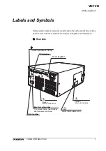
Страница 156: ...VISY218...

Страница 157: ...roduced or distributed without the express written permission of OLYMPUS MEDICAL SYSTEMS CORP OLYMPUS is a registered trademark of OLYMPUS CORPORATION Trademarks product names logos or trade names use...

Страница 158: ...y Road 12 01 04 Valley Point Office Tower Singapore 248373 Fax 6834 2438 Telephone 6834 0010 A8F Ping An International Financial Center No 1 3 Xinyuan South Road Chaoyang District Beijing 100027 P R C...

Страница 159: ...INSTRUCTIONS COMPACT TROLLEY TC C2 VISY218...

Страница 160: ...Olympus endoscopic imaging system for diagnosis treatment and photodocumentation Do not use the equipment for any purpose other than its intended application The safety and performance of an endoscop...

Страница 161: ...CONTENTS PAGE 1 INTRODUCTION 1 2 SPECIFICATIONS 2 3 SAFETY PRECAUTIONS 3 4 INSTRUCTIONS 4 5 MANOEUVRING TRANSPORTATION 7 6 CARE STORAGE AND MAINTENANCE 7 7 SPARES 9 8 ACCESSORIES 9 VISY218...

Страница 162: ...pus office if any parts are damaged or missing FIGURE 1 1 Instructions Top shelf removable Keyboard tray Second shelf fixed Third shelf adjustable Base tray Plain castor Brake castor M6 hand wheel x2...

Страница 163: ...hould not exceed the size of the shelf Castors 4 x 100mm non antistatic two with brakes Isolation Transformer storage Located in the base tray designed to hold the Olympus MB 631 isolation transformer...

Страница 164: ...exceeded by the equipment connected to it 3 7 Keep open containers of liquid away from electrical equipment used on the trolley to prevent operator electrical shock and equipment damage Do not use the...

Страница 165: ...helf to maintain an even balance Remove the four M6 screws adjust the shelf position then replace the four screws tightening to a torque of 10 5Nm D If a monitor is to be used it is best fitted before...

Страница 166: ...strap as required to remove any slack CAUTION The TC C2 has been designed for use with 14 CRT monitors or 15 18 19 LCD monitors when used with the MAJ 197 LCD monitor mount see Section 8 for part numb...

Страница 167: ...agon driver provided Secure the scope pole assembly to the TC C2 as shown FIGURE 4 3 Scope pole assembly M6 thumbwheel M6 plastic washer Spacer M6 screw M6 crinkle washer M6 plain washer Scope hanger...

Страница 168: ...quirements of EN IEC 60601 1 1 the safety standard for medical electrical systems This standard requires the aggregate earth leakage current of items powered via a plugblock to be less than 0 5mA This...

Страница 169: ...every care has been taken to maximise the stability of this product care must be exercised when moving it particularly over uneven surfaces or trailing cables to avoid tipping 5 5 It is recommended t...

Страница 170: ...gularly If necessary retighten the screws using the ball driver supplied 7 SPARES Instructions K5070322 Webbing strap 3025357 Guard rail LH K7503496 Guard rail RH K7503594 Foot holder 7272472 M6 x 12...

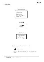
Страница 171: ...VISY218...

Страница 172: ...VISY218...

Страница 173: ...VISY218...

Страница 174: ...KeyMed House Stock Road Southend on Sea Essex SS2 5QH United Kingdom Fax 01702 465677 Telephone 01702 616333 2951 Ishikawa cho Hachioji shi Tokyo 192 8507 Japan Fax 042 646 2429 Telephone 042 642 2111...

Отзывы: