E17
40838301TH Rev.1
A3 - 16
A3.1.12 E17 Circuit Diagram
1.
Block diagram
The circuit diagram shown on page 13/16 consists of the following connector:
•
Connector CN1 that provides an interface between E17 board and main power supply
unit.
2.
Function
1)
Sensors and switch control
Six types of sensors are used in the printer as listed below. All of their output enter CPU
ports for referring to and processing by the CPU.
Figure A3.1.15 shows sensors and switch control.
•
Inlet sensor 1 and 2
•
Write sensor (To detect the paper top position for printing)
•
Outlet sensor
•
Paper end sensor
•
Toner end sensor
•
Cover status switch
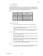
The functions of various sensors are described in the following table.
Sensor Type
PSIN-N
PSIN2-N
Inlet sensor
Inlet sensor 2
This photosensor is positioned before the resist roller to detect whether
the paper has entered into the printer section.
Sensor Name
Function
WRSNS-N
Write sensor
Detects the arrival of paper at designated position on the paper transport
route inside the printer in order to turn on the light of the LED head.
0: Paper exists, 1: Paper does not exist
PSOUT-N
Outlet sensor
Located at the exit of the printer to supervise the paper exit operation.
0: Paper exists, 1: Paper does not exist
PAPER-N
Paper sensor
Detects the presence of paper in the paper cassette.
0: Paper exists, 1: Paper does not exist
TNRSNS-N
Toner sensor
Detects the remaining toner in the toner cartrige.
"The length of time of low-toner state within fixed time interval" detects a
low-toner state.
CVOPN-N
Cover open
sensor
Detects whether the cover of the printer section is open or not.
0: Cover is open, 1: Cover is close
Содержание OKIFAX 5400
Страница 7: ...40838301TH Rev 1 CHAPTER 1 GENERAL INFORMATION...
Страница 46: ...40838301TH Rev 1 CHAPTER 2 INSTALLATION PROCEDURE...
Страница 130: ...40838301TH Rev 1 CHAPTER 3 BRIEF TECHNICAL DESCRIPTION...
Страница 138: ...40838301TH Rev 1 CHAPTER 4 MECHANICAL DISASSEMBLY AND REASSEMBLY...
Страница 157: ...40838301TH Rev 1 CHAPTER 5 ADJUSTMENTS...
Страница 162: ...40838301TH Rev 1 CHAPTER 6 CLEANING AND MAINTENANCE...
Страница 189: ...40838301TH Rev 1 CHAPTER 7 TROUBLESHOOTING AND REPAIR FOR OKIFAX 5400...
Страница 240: ...40838301TH Rev 1 CHAPTER 8 DIPSWITCHS SETTING TABLES...
Страница 353: ...40838301TH Rev 1 Appendix B Descriptions of Print Operation First Edition August 1999 Oki Data Corporation...
Страница 375: ...40838301TH Rev 1 Appendix C Circuit Diagram and Parts List OK IFAX 5400 First Edition August 1999 Oki Data Corporation...
Страница 380: ...40838301TH Rev 1 D 2 SECTION 1 CABINET ASSEMBLY 5...
Страница 382: ...40838301TH Rev 1 D 4 SECTION 2 CONTROL PANEL ASSEMBLY...
Страница 384: ...40838301TH Rev 1 D 6 SECTION 3 PRINTER ASSEMBLY 51...
Страница 387: ...40838301TH Rev 1 D 9 SECTION 4 BASE ASSEMBLY 30 37 36 39 40 5...
Страница 390: ...40838301TH Rev 1 D 12 SECTION 5 SCAN UNIT...
Страница 392: ...40838301TH Rev 1 D 14 SECTION 6 PAPER GUIDE U ASSEMBLY...
Страница 394: ...40838301TH Rev 1 D 16 SECTION 7 CABLES 10 11 19 12 20 21...
Страница 396: ...40838301TH Rev 1 D 18 SECTION 8 OPTION TELEPHONE US...
Страница 399: ...40838301TH Rev 1 D 21 SECTION 8 OPTION TELEPHONE UK ITA NOR DEN BEL...
Страница 402: ...40838301TH Rev 1 D 24 SECTION 8 OPTION TELEPHONE HOL GER FRA SWITZ AUT INT L...
Страница 405: ...40838301TH Rev 1 Appendix E Board Layout OKIFAX 5400 First Edition August 1999 Oki Data Corporation...
Страница 424: ...40838301TH Rev 1 F 15 5 2 PCB Layout TQSB 2PCB PU FG CONTROLLER MOTOR DRIVER SEN2 MOTOR OSC SEN1...
Страница 425: ...40838301TH Rev 1 F 16 Figure 6 1 6 PARTS LIST SECTION1 CABINET CASSETTE ASSEMBLY F 16 1 4 P 6 5 8 7 3 O 1 2...
Страница 426: ...40838301TH Rev 1 F 17 SECTION2 MECHANICAL ASSEMBLY Figure 6 2 F 16 2 9 A 0 C M L D N E F G H U V T S Q R J I B K A A B B...
Страница 428: ...40838301TH Rev 1 Appendix G RMCS SYSTEM MANUAL For Model 20 First Edition August 1999 Oki Data Corporation...


