4-5
CHAPTER 4 REPAIR PROCEDURES
7. Unsolder the Load Cell wiring from the Main PC Board. Note the position and color coding of the
wires on the main PC Board. These will have to be soldered on the new PC Board in the same
positions.
8. On the replacement Main PC Board, install the Battery and Switch connectors.
9. Refer to Figure 3-2 and solder the Load Cell wiring to the replacement Main PC Board. Make sure
that the color coded wiring is installed in the correct locations.
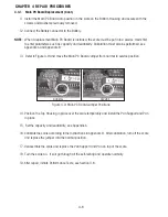
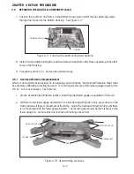
10. Connect the Display Cable to the Main PC Board connector. See Figure 4-8.
CAUTION: THE DISPLAY CABLE CONNECTOR MUST BE CORRECTLY INSTALLED WITH THE TAB FACING UP.
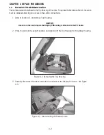
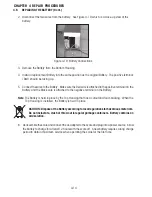
6. Remove the Battery connector plug from the Main PC Board and the connector that connects
to the On/Off Switch. See Figure 4-7.
4.3.1 Main PC Board Replacement (Cont.)
Figure 4-7. Disconnecting Battery and On/Off Switch Connectors from Main PC Board.
ON/OFF SWITCH CONNECTOR
BATTERY CONNECTOR
LOAD CELL WIRING
DISPLAY CABLE
DISPLAY CABLE CONNECTOR
CONNECTOR TAB
Figure 4-8. Installing Display Cable to Main PC Board.
MAIN PC BOARD
Содержание EC Series
Страница 2: ......
Страница 4: ......
Страница 14: ...2 6 CHAPTER 2 DIAGNOSIS...
Страница 30: ...3 16 CHAPTER 3 SCALE TESTING AND CALIBRATION...
Страница 52: ...A 4 APPENDIX A SERVICE MODES...
Страница 55: ......
Страница 56: ...PN 80010584 B SERVICE MANUAL EC SERIES SCALES 80010584...

