2-2
CHAPTER 2 DIAGNOSIS
REMEDY
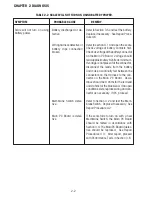
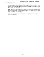
Refer to Section 3.5 and test the battery.
Replace if necessary. See Repair Proce-
dure 4.6.
Refer to section 4.1 and open the scale.
Check voltage at battery contacts first.
Check dc voltage at the battery connector
on the Main PC Board. Voltage should
read approximately 6 Volts dc minimum.
If voltage is not present at the connector,
disconnect the leads from the battery
and make a continuity test between the
connectors on the Harness to the con-
nector on the Main PC Board. Resis-
tance should be 0 ohms for the red lead
and 0 ohms for the black lead. If an open
condition exists, replace wiring and con-
nector as necessary. If OK, proceed.
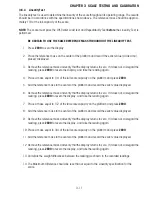
Refer to Section 3.2 and test the Mem-
brane Switch. Replace if necessary. See
Repair Procedure 4.2
If the scale fails to turn on with a new
Membrane Switch, the Main PC Board
should be tested in accordance with
Section 3.4. The Main PC Board if defec-
tive should be replaced. See Repair
Procedures 4.3. After repair, proceed
with Performance Tests in Section 3.6.
PROBABLE CAUSE
Battery discharged or de-
fective.
Wiring harness defective or
battery clips connection
broken.
Membrane Switch defec-
tive.
Main PC Board is defec-
tive.
SYMPTOM
Scale will not turn on using
battery power.
TABLE 2-2 SCALE WILL NOT TURN ON USING BATTERY POWER.
Содержание EC Series
Страница 2: ......
Страница 4: ......
Страница 14: ...2 6 CHAPTER 2 DIAGNOSIS...
Страница 30: ...3 16 CHAPTER 3 SCALE TESTING AND CALIBRATION...
Страница 52: ...A 4 APPENDIX A SERVICE MODES...
Страница 55: ......
Страница 56: ...PN 80010584 B SERVICE MANUAL EC SERIES SCALES 80010584...


