3-4
CHAPTER 3 SCALE TESTING AND CALIBRATION
3.4 TESTING THE MAIN PC BOARD
The Main PC Board can be tested by measuring voltages and by using a simulator. The simulator replaces
the Load Cell during testing and is a useful tool for diagnosing problems.
3.4.1 Main PC Board Voltage Measurements
Prior to making the voltage measurements, the battery should have been fully charged and tested.
1. Disconnect power from the scale.
2. Remove the Top housing, refer to Section 4.1 and leave the Membrane Switch connected to the
scale.
3. Disconnect the battery from the Main PC Board.
4. Remove screws and washers holding the Main PC Board and lift the board and lay flat.
5. Connect the AC Adapter to the scale.
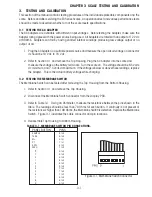
6. Refer to Figure 3-2, Interconnection Diagram which illustrates the interconnections to the Main PC
Board and is shown as a top view.
7. Turn the scale on.
8. Using a DVM, measure the excitation voltage EXE and -EXE leads it should be 5 volts dc.
This is the excitation voltage for the Load Cell and is regulated. If the voltage is lower, replace the
Main PC Board, refer to Section 4.3 and then proceed with Performance Tests in accordance with
Section 3.6.
9. Measure incoming power from the AC Adapter connector shown in Figure 3-2. The voltage should
read above 6 Volts dc with power on.
10. Connect the battery to the Main PC Board and measure the voltage across Black and Red leads on
the battery connector. The full battery voltage should read a minimum of 6.0 Volts dc. If the voltage
is lower, the battery may require charging or it may be defective. Refer to section 3.5 and test the
battery.
11. Perform simulator testing.
Содержание EC Series
Страница 2: ......
Страница 4: ......
Страница 14: ...2 6 CHAPTER 2 DIAGNOSIS...
Страница 30: ...3 16 CHAPTER 3 SCALE TESTING AND CALIBRATION...
Страница 52: ...A 4 APPENDIX A SERVICE MODES...
Страница 55: ......
Страница 56: ...PN 80010584 B SERVICE MANUAL EC SERIES SCALES 80010584...


