


System instructions OBO isCon
®
EN | 49
Installing the isCon® system
5 6
Attaching the potential connection
If there is a direct lightning strike to the air-termination rod, the incoming
energy is run through the connected isCon
®
conductor to the building's
lightning conductor system. To prevent surface discharge moving away
along the surface, the isCon
®
conductor must be connected to the equi-
potential bonding of the structure in the area of the two connection points.
The potential connection can be made via metallic and earthed roof struc-
tures, generally earthed parts of the building structure and via the protec-
tive conductor of the low-voltage system.
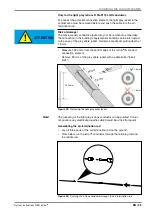
WARNING
Risk of function loss!
Metallic chips from the connection area of the cable could cause a short
circuit between the connection element and potential connection if there
is a lightning strike.
This can disrupt the arresting function of the insulated cable. Floating
discharges may occur.
After installation, clean the connection area of metallic chips.
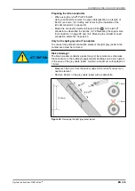
WARNING
Danger of lightning currents entering the building!
If, during a thunderstorm, a lightning strike runs lightning currents into
the building, the coupled currents can destroy devices, cause fires and
endanger lives.
If there is a lightning strike, the equipotential bonding must not carry light-
ning current and must be in the protection angle of the lightning protection
system.
Note!
If you use the light grey isCon
®
conductor, you must remove the grey
cable jacketing before connecting the potential connection (see “„5.1.1
Removing the light grey protective jacket (isCon® ProPI 75 LGR)“ on
page 28).
Note!
Before attaching a potential connection element (e.g. clip), clean the
black jacket of the isCon
®
conductor from grease and other impurities
using a cleaning cloth, type isCon
®
EPPA 004 (Art. No. 5408 060), to
improve the electrical conductivity.
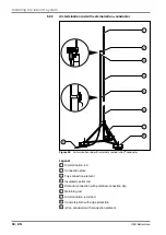
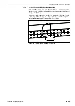
5 6 1
Installing the potential connection on an insulated air-termination
rod
Note!
The isCon
®
conductor, type isCon
®
Basic 45, does not require an equipo-
tential bonding connection on the internal or external potential connection
element
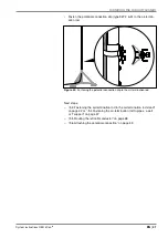
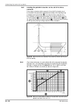
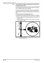
With a calculated separation distance of s ≤ 0.75 metres, a distance of
x = 1.5 metres must be maintained between the top connection element
and the following connection for the equipotential bonding (see Figure
13 on page 21, No.
4
). The design of the isFang air-termination rod
provides this distance through its 1.5 metre-long central rod.
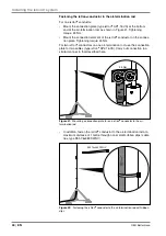
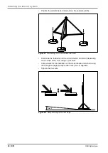
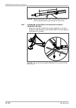
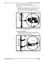
The potential connection on the insulated air-termination rod must be
designed differently for air-termination rods with internal and external
conductors.
Содержание isCon BA 45 SW
Страница 1: ...01 2018 EN isCon System instructions Building Connections...
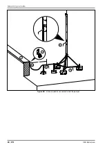
Страница 60: ...OBO Bettermann 60 EN Mounting variants x 1 2 6 5 3 4 Figure 65 isCon conductor connected to metallic parapet...
Страница 66: ...OBO Bettermann 66 EN Own notes...
Страница 67: ...System instructions OBO isCon EN 67 Own notes...


