


OBO Bettermann
22 | EN
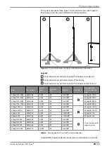
Planning an installation
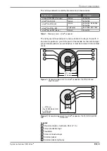
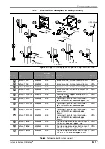
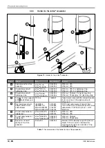
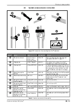
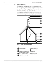
Legend:
1
Air-termination system
DIN EN 62305-3 (IEC 62305-3, VDE 0185-305-3) Section 5.2 must
be taken into account when planning the design of the air-termination
system. The height and arrangement of the air-termination system
must be designed in such a way that the objects to be protected are
located in the protection area.
2
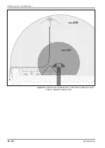
Protection area
Along the whole of its length, the conductor must be located in the
protection area of the air-termination system. α = Protective angle ac-
cording to DIN EN 62305 (IEC 62305, VDE 0185-305-3).
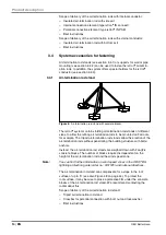
3
Connection element
The connection element may only be connected to the air-termination
system or forwarding conductor of the external lightning protection.
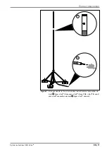
4
Required separation distance to first potential connection
No electrically conductive or earthed parts may be located in the
area of the potential connection within the radius of the calculated
separation distance. These include metallic construction parts, cable
brackets and reinforcements.
5
Potential connection
The potential connection must be installed in the manner described
in “„5.6 Attaching the potential connection“ on page 49. The
potential connection element must be connected to the equipotential
bonding with ≥ 6 mm² Cu or an equal conductivity.
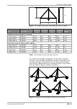
6
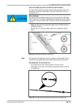
Bend radius
When routing cables, do not go below the minimum radii.
7
Additional potential connections
After the first potential connection using the potential connection
element, the isCon
®
conductor can be connected multiple times with
the earthed components of the structure, through which the lightning
current does not flow. See also “„5.6.4 Installing additional potential
connections“ on page 55.
8
Cable fastening
The isCon
®
conductor must be fastened using the installation mate-
rial indicated. The maximum distance between the fastenings is 1
metre.
9
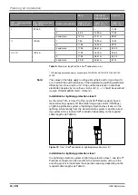
Separation distance of s ≤ 17 5 cm in air
A potential connection is not required for a calculated separation
distance of s ≤ 17.5 cm in air.
Note:
Before designing the lightning protection system, obtain information on
the function, general design and location of the structure.
Note:
During routing in buildings, pay attention to the specified protection meas-
ures, e.g. division into fire sections. Read the OBO fire protection guide
(article number: 9134859) for more information.
Содержание isCon BA 45 SW
Страница 1: ...01 2018 EN isCon System instructions Building Connections...
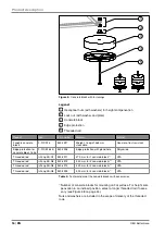
Страница 60: ...OBO Bettermann 60 EN Mounting variants x 1 2 6 5 3 4 Figure 65 isCon conductor connected to metallic parapet...
Страница 66: ...OBO Bettermann 66 EN Own notes...
Страница 67: ...System instructions OBO isCon EN 67 Own notes...


