


System instructions OBO isCon
®
EN | 23
Planning an installation
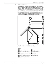
4 2
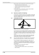
Calculating, checking and maintaining the separation
distance
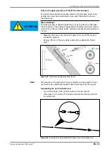
Note:
If the approval authorities, the insurance company or the customer has
not yet specified whether the appropriate building should be protected
by a lightning protection system, we recommend that the lightning pro-
tection planner carry out a risk evaluation according to DIN EN 62305-2 /
IEC 62305-2, which will indicate whether a lightning protection system is
required or not.
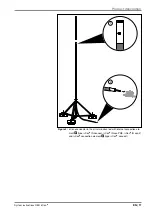
• Calculate the separation distance at the connection point of the
isCon
®
conductor according to DIN EN 62305-3 (VDE 0185-305-3)/
IEC 62305-3 Section 6.3. Measure the distance (l) from the connection
point of the isCon
®
conductor to the next level of the lightning protec-
tion equipotential bonding, e.g. earthing system, metal parapet of the
construction with electrically connected metal facade or steel rein-
forcement (high-rise building).
• Check whether the calculated separation distance (s) is less than or
equal to the specified equivalent separation distance of the isCon
®
conductor.
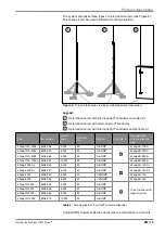
• If the specified equivalent separating distance is exceeded, then you
must install additional conductors:
– The current is split up if you install multiple insulated cables in par-
allel. The reduced current division coefficient k
c
thus also reduces
the calculated separation distance (s).
– We recommend installing the cables at least 20 cm apart. This
keeps the magnetic fields to a minimum, preventing the cables
from influencing each other.
– When cables are routed directly beside one another, the inductivity
of the total arrangement is not reduced by the factor n and the cur-
rent division coefficient k
c
is not reduced accordingly.
– Install the cables as far apart from each other as possible, if the
installation conditions permit this. Ideally, the second cable should
be run to the ground on the other side of the building.
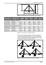
4 3
Cable lengths and lightning protection classes
The possible length of an isCon
®
conductor can be calculated using the
following formula, according to the calculated separation distance (s),
the lightning protection class (k
i
), the number of cables used (k
c
) and the
electrical insulation (k
m
) (see DIN EN 62305-3):
L(m) =
s • k
m
k
c
• k
i
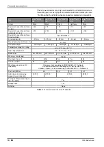
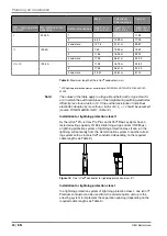
The following Table 9 offers an example of the maximum possible lengths
of the isCon
®
conductor at a separation distance s = 0.75 metres in air.
Should the cable lengths shown there be insufficient for the construction
project, we recommend having a lightning protection specialist carry out a
detailed calculation of the factor k
c
using the building data. The above for-
mula shows that longer cable lengths are possible with a greater number
of conductors and thus the reduction of the factor k
c
.
Содержание isCon BA 45 SW
Страница 1: ...01 2018 EN isCon System instructions Building Connections...
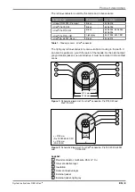
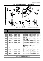
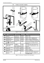
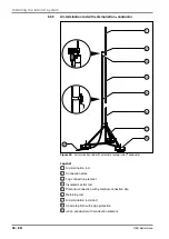
Страница 60: ...OBO Bettermann 60 EN Mounting variants x 1 2 6 5 3 4 Figure 65 isCon conductor connected to metallic parapet...
Страница 66: ...OBO Bettermann 66 EN Own notes...
Страница 67: ...System instructions OBO isCon EN 67 Own notes...


