Oasis RAPID PRO RP14 Скачать руководство пользователя страница 35


Page 34 of 43


Maintenance & Information 


CHECKS TO THE REFRIGERATION EQUIPMENT 

Where electrical components are being  changed, they shall be fit for the purpose and to the correct 
specification. At all times the manufacturer's maintenance and service guidelines shall be followed. If 
in doubt consult the manufacturer's technical department for assistance.  

The following checks shall be applied to installations using flammable refrigerants: 


The charge size is in accordance with the room size within which the refrigerant containing parts 
are installed; 


The ventilation machinery and outlets are operating adequately and are not  obstructed; If an 
indirect  refrigerating  circuit  is  being  used,  the  secondary  circuit  shall  be  checked  for  the 
presence of refrigerant; 


Marking  to  the  equipment  continues  to  be  visible  and  legible.  Markings  and  signs  that  are 
illegible shall be corrected; 


Refrigeration  pipe  or  components  are  installed  in  a  position  where  they  are  unlikely  to  be 
exposed to  any  substance  which  may corrode  refrigerant  containing  components,  unless  the 
components are constructed of materials which are inherently resistant to being corroded or are 
suitably protected against being so corroded. 

CHECKS TO ELECTRICAL DEVICES 

Repair  and  maintenance  to  electrical  components  shall  include  initial  safety  checks  and  component 
inspection procedures. If a fault exists that could compromise safety, then no electrical supply shall be 
connected to the circuit until it is satisfactorily dealt with. If the fault cannot be corrected immediately 
but it is necessary to continue operation, an adequate temporary solution shall be used. This shall be 
reported to the owner of the equipment, so all parties are advised. 

Initial safety checks shall include: 


That  capacitors  are  discharged:  this  shall  be  done  in  a  safe  manner  to  avoid  possibility  of 
sparking; 


That there no live electrical components and wiring are exposed while charging, recovering or 
purging the system; 


That there is continuity of earth bonding. 

CABLING 

Check that cabling will not be subject to wear, corrosion, excessive pressure, vibration, sharp edges or 
any other adverse environmental effects. The check shall also consider the effects of aging or continual 
vibration from sources such as compressors or fans. 

REPAIR TO INTRINSICALLY SAFE COMPONENTS 

Do not apply any permanent inductive or capacitance loads to the circuit without ensuring that this will 
not exceed the permissible voltage and current permitted for the equipment in use. 

Intrinsically safe components are the only types that can be worked on while live in the presence of a 
flammable atmosphere. The test apparatus shall be at the correct rating. Replace components only 
with parts specified by the manufacturer. Other parts may result in the ignition of refrigerant in the 
atmosphere from a leak. 


Содержание RAPID PRO RP14

Страница 1: ......

Страница 2: ...ur invoice as proof of purchase provide further information relating to the issue including any photos or videos have completed the online warranty registration or provide a completed warranty card On...

Страница 3: ...Note 5 Specifications 7 Modes Codes 8 Quick Start Guide 10 Safety 11 Location of Installation and Airflow Clearance 12 Installation Connection 16 Controller Operation 22 WiFi Settings 28 Troubleshoot...

Страница 4: ...ith minimal running costs Designed with the latest technology including stepless full DC inverter compressors fans and control systems the Oasis iX series is the energy efficient and environmentally f...

Страница 5: ...lar inspection of the condensate drain to detect any obstructions or debris accumulation It is important to keep the drain clean to allow for smooth condensate flow and proper discharge to the drainag...

Страница 6: ...4 9 COPat 50 capacity 7 2 7 5 7 2 7 4 7 4 7 4 7 4 COPat 20 capacity 7 9 8 8 8 0 8 8 8 1 8 1 8 0 Air 35 C Water 28 C Cooling capacity kW 6 3 9 0 10 0 11 3 15 0 15 0 19 5 Sound Pressure at 1m dB A 37 8...

Страница 7: ...G H RP14 402 574 389 432 945 340 73 660 RP16 402 674 389 432 1045 370 73 660 RP18 402 674 389 432 1045 380 73 660 RP22 402 824 389 432 1195 470 73 760 RP32 511 891 498 536 1264 570 73 956 RP32T 511 89...

Страница 8: ...20 Fast heating intelligent optimization according to ambient temperature and water temperature Energy efficiently saving Smart mode Heating capacity 100 20 Intelligent optimization according to ambie...

Страница 9: ...ainage point The unit must sit level to allow condensation to drain correctly The schematic diagram is for reference only Please check the water inlet outlet label on the heat pump while plumbing the...

Страница 10: ...t be running and water circulating through the heat pump for the system to operate 1 Turn on your water pump and check for water leaks and verify water flow to and from the pool 2 Turn on the electric...

Страница 11: ...system After a stoppage the unit will not start for at least 3 minutes Do not use any means to accelerate the defrosting process or to clean other than those recommended by the manufacturer If install...

Страница 12: ...nt space for unobstructed airflow into and out of the heater At least 3 5m away from the water s edge No greater than 7 5m from the water s edge to avoid heat loss from the piping No greater than 5 0m...

Страница 13: ...th the specifications on Page 5 of this manual Location Connect the unit in the pool pump discharge return line downstream of all filter and pool pumps and upstream of any chlorinators ozonators or ch...

Страница 14: ...nit Optimal water flow rates are listed on Page 5 of this manual It is imperative that water flow is kept as close as possible to these flow rates Correct water flow not only offers optimal heater per...

Страница 15: ...install the drainage barbs Condensate Drain Barbs Fit the condensate drain barbs into the 2 holes under the unit if you need to direct water away from the heater If the barb is too stiff place it in h...

Страница 16: ...onal circuit protection device must be installed between the heater and the water circulation pump if a water pump is hard wired into the heater Please note recommended circuit breaker sizes make no a...

Страница 17: ...r 3 seconds to unlock lock screen After screen is unlocked press it to select mode Auto 12 40 C 54 F 104 F Heating 18 40 C 64 F 104 F Cooling 12 30 C 54 F 86 F Speed Select Turbo Smart Silence mode Up...

Страница 18: ...splay Real time power consumption function available for single phase only Mode Selection Press to select mode Auto adjustable temperature range 12 40 C 54 F 104 F Heating adjustable temperature range...

Страница 19: ...n press once to cancel the setting Time display When the machine is off the time display on the top right corner is real time When the machine is on the real time can be shown 10 seconds if you press...

Страница 20: ...etting After setting the icon in the lower left corner indicates as below Timer on every day Timer off every day Timer on every day No timer off and alternate display Timer on every day Timer off one...

Страница 21: ...er the Parameter Modification mode press or to change the values then press to confirm and quit Parameter Modification mode press to quit Parameter Checking status No Content Adjust Range Step Length...

Страница 22: ...ll status points and their corresponding value through or Press to quit running status checking mode Symbol Content Unit C0 Inlet water temp C F C1 Outlet water temp C F C2 Ambient temp C F C3 Exhaust...

Страница 23: ...oting purposes App Installation To download simply visit your device s app store and search for Inverter Life App Set Up Create an Account In order to take advantage of the app you must first register...

Страница 24: ...IGURED AT 2 4 GHZ AND THE BLUETOOTH FUNCTION IS ENABLED Auto Discovery Bluetooth Press for 3 seconds after the screen unlock will be flashing rapidly to enter Wi Fi connection status Click Add Device...

Страница 25: ...screen unlocks will be flashing rapidly to enter Wi Fi connection status Click Add device and follow the instructions below to finish connection display on the screen once the Wi Fi connection success...

Страница 26: ...cess Note If it doesn t jump automatically click Confirm hotspot connection next NOTE If connect fails please make sure your network name and password are correct And your router mobile phone and devi...

Страница 27: ...Page 26 of 43 WiFi Settings Operation Menu The following instructions are for heat pumps with heating and cooling functions...

Страница 28: ...y members also want to control the device Once your family members also register on the app initially subsequent operations can be conducted by the administrator as follows The following pictures are...

Страница 29: ...aust temp protection EA Evaporator overheat protection only at cooling mode P0 Controller communication failure P1 Water inlet temp sensor failure P2 Water outlet temp sensor failure P3 Gas exhaust te...

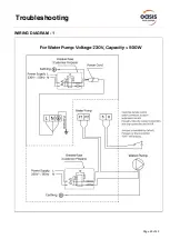
Страница 30: ...Page 29 of 43 Troubleshooting WIRING DIAGRAM 1...

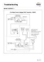
Страница 31: ...Page 30 of 43 Troubleshooting WIRING DIAGRAM 2...

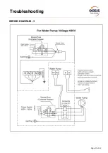
Страница 32: ...Page 31 of 43 Troubleshooting WIRING DIAGRAM 3...

Страница 33: ...your local service agent details Should I check my unit regularly We recommend you check your unit regularly to avoid potential issues and damage to your heat pump What should I be checking regularly...

Страница 34: ...eres Ensure that the leak detection equipment being used is suitable for use with flammable refrigerants i e non sparking adequately sealed or intrinsically safe PRESENCE OF FIRE EXTINGUISHER If any h...

Страница 35: ...cks and component inspection procedures If a fault exists that could compromise safety then no electrical supply shall be connected to the circuit until it is satisfactorily dealt with If the fault ca...

Страница 36: ...TECTION OF FLAMMABLE REFRIGERANTS Under no circumstances shall potential sources of ignition be used in the searching for or detection of refrigerant leaks A halide torch or any other detector using a...

Страница 37: ...nts are removed safely When transferring refrigerant into cylinders ensure that only appropriate refrigerant recovery cylinders are employed Ensure that the correct number of cylinders for holding the...

Страница 38: ...d operate in accordance with manufacturer s instructions h Do not overfill cylinders No more than 80 volume liquid charge i Do not exceed the maximum working pressure of the cylinder even temporarily...

Страница 39: ...ce contact Oasis on 1800 815 913 or via our Service Request page on our web site provide a copy of your invoice as proof of purchase provide further information relating to the issue including any pho...

Страница 40: ...viously unboxed unit s On Commercial Installations such as but not exclusively health clubs swim schools motels hotels and hydrotherapy parts and in field labour warranty the warranty period is limite...

Страница 41: ...ty does not cover the following a Natural Disasters hail lightening flood fire etc b Rust or damage to paintwork caused by a corrosive atmosphere c When a unit is installed by an unqualified person d...

Страница 42: ...ect s Its use is beyond the control of the author contributor publishers and distributors and should not be relied upon without consulting your local Professional for comprehensive advice This guide i...

Страница 43: ...Page 42 of 43 Notes...

Страница 44: ...u 1800 815 913 ABN 87 858 371 003 Head Office 6 8 Austral Place Hallam VIC 3803 New South Wales Unit 2 10 Boden Road Seven Hills NSW 2147 Queensland 11 Andy Court Upper Coomera QLD 4209 New Zealand Oa...

Отзывы: