


Page 15 of 43
Installation & Connection
Electrical Connection
Ensure the power cable and circuit protection device are of a suitable size for the heater being
installed. Also check that there is adequate voltage and current available at the heater connection to
run the unit.
Voltage range should be 220-240 volts for single phase, and 380-415 volts for 3 phase units. Voltage
ranges outside these parameters will cause heater damage and void your warranty.
1. Ensure power is disconnected during installation or service.
2. Always comply with the national and local electrical codes and standards.
3. Ensure the electrical cable size is adequate for heater requirements at the installation location.
4. The heater must be equipped with appropriate circuit protection and isolation devices.
5. An additional circuit protection device must be installed between the heater and the water circulation
pump if a water pump is hard-wired into the heater. Please note recommended circuit breaker sizes
make no allowance for a water pump hard wired into the heater.
6. The unit must be well earthed. Remove the front panel to access the electrical connection terminals
of the heater. The electrical wiring diagram is affixed to the inside of the front panel or at the back of
this manual.
Heater electrical installation undertaken by an unlicensed installer will void the
warranty. Correct installation is required to ensure safe and efficient operation of
your pool heater.
A licensed electrician must read the installation manual before connecting.
Use a cross screwdriver to remove the two screws
located at the bottom of the right-side panel.
Detach the lower half of the panel.
Proceed to unscrew the four screws on the cover of
the electrical box.
Connect the terminals following the electrical
diagrams.
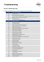
Содержание RAPID PRO RP14
Страница 1: ......
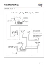
Страница 30: ...Page 29 of 43 Troubleshooting WIRING DIAGRAM 1...
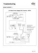
Страница 31: ...Page 30 of 43 Troubleshooting WIRING DIAGRAM 2...
Страница 32: ...Page 31 of 43 Troubleshooting WIRING DIAGRAM 3...
Страница 43: ...Page 42 of 43 Notes...


