background image


3   


                    Version 0.2


SCS-1002


Hospital and refrigerator alarm system


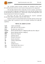
This  operating  manual  describes  Hospital  and  refrigerator  alarm  system  

SCS-1002 (hereinafter referred to as the System) and any options of its composition.  

This operating manual describes composition, structure, operation, specifications 

of the System and its components, instructions for the correct and safe operation of the 
System (intended use, technical service, current repair, storage and transportation), and 
disposal instructions for the System components. 

          Only  those  who  have  read  and  understood  the  System’s  operational 
documentation shall be permitted to operate with the System. 

Only those who have read and understood this document and those who have had 

special  training  shall  be  permitted  to  service  the  System  according  to  the  applicable 
regulations. 

TERMS AND ABBREVIATIONS 

LCD 

Liquid-crystal display  

SPTA 

Spare parts, tools and accessories 

RCD 

Reception and control device 

Register 

Russian Maritime Register of Shipping and Russian River Register 

RMRS 

Russian Maritime Register of Shipping 

RRR 

Russian River Register 

OM 

Operating manual 

SCS 

Personnel call system 

SC 

System components 

TR 

Technical requirements 

CL 

Check list 

TS 

Technical service 

ТS-1 

Semi-annual technical service 

ТS-2 

Annual technical service 


Содержание SCS-1002

Страница 1: ...tr 192174 Phone 7 812 622 23 10 info unicont com St Petersburg Russia Fax 7 812 362 76 36 www unicont com Limited Liability Company NPK MORSVYAZAVTOMATICA HOSPITAL AND REFRIGERATOR ALARM SYSTEM SCS 1002 Operating manual ...

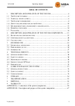
Страница 2: ...D CONTROL DEVICES 15 2 2 CONTROLLERS OF CALL BUTTONS 20 2 3 CALL BUTTONS 22 3 INTENDED USE 24 3 1 OPERATIONAL LIMITATIONS 24 3 2 PREPARATIONS TO USE 24 3 3 INTENDED USE 27 4 TECHNICAL SERVICE 30 4 1 GENERAL INSTRUCTIONS 30 4 2 SAFETY FEATURES 30 4 3 MAINTENANCE ROUTINE 30 4 4 INSTRUCTIONS ON SPTA KIT 32 4 5 PRESERVATION 32 5 CURRENT REPAIR OF THE SYSTEM 33 5 1 GENERAL INSTRUCTIONS 33 5 2 SAFETY FE...

Страница 3: ...ad and understood the System s operational documentation shall be permitted to operate with the System Only those who have read and understood this document and those who have had special training shall be permitted to service the System according to the applicable regulations TERMS AND ABBREVIATIONS LCD Liquid crystal display SPTA Spare parts tools and accessories RCD Reception and control device...

Страница 4: ...rameter Value Quantity of controllers pcs 1 5 10 32 Power supply voltage V SCs 24 DC Signaling devices 24 DC or 220 AC frequency 50 Hz Integrated protection galvanic isolation from the mains power reverse polarity galvanic isolation of signaling circuits faulty connection of call buttons communication failure with controllers Power consumption defined by the total power of the SC included in the s...

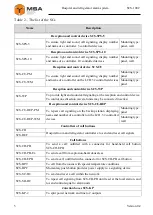
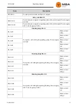
Страница 5: ...veral units may be connected in series Reception and control device SCS CU REP SCS CU REP PM To repeat call signaling on the backup station displaying name and number of a controller on the LCD 32 controlled devices Mounting type panel SCS CU REP WM Mounting type wall Controllers of call buttons SCS CH Hospital room and refrigerator controllers to send and reset call signals SCS REF Call buttons S...

Страница 6: ... call with light signaling pulse Power supply 24 V DC Dome colour white FL 24 G Dome colour green FL 24 B Dome colour blue FL 24 R Dome colour red FL 24 О Dome colour orange Rotating lamp RL 24 RL 24 G To repeat a call with light signaling flashing Power supply 24 V DC Dome colour green RL 24 B Dome colour blue RL 24 R Dome colour red RL 24 О Dome colour orange Rotating lamp RL 220 RL 220 G To rep...

Страница 7: ...ncy 50 Hz Dome colour green RFL 220 B Dome colour blue RFL 220 R Dome colour red RFL 220 О Dome colour orange Light and sound signaling unit AL 24 AL 24 W To repeat a call with light and sound signaling Power supply 24 V DC Dome colour white AL 24 G Dome colour green AL 24 B Dome colour blue AL 24 R Dome colour red AL 24 О Dome colour orange Light and sound signaling unit AL 220 AL 220 W To repeat...

Страница 8: ...r supply 220 V AC frequency 50 Hz Dome colour white L 220 G Dome colour green L 220 B Dome colour blue L 220 R Dome colour red L 220 О Dome colour orange Sound signaling unit A A 24 To repeat a call with sound signaling Power supply 24 V DC A 220 To repeat a call with sound signaling Power supply 220 V AC frequency 50 Hz Light signaling unit PGS VSPYSHKA 24 PGS VSPYSHKA 24 To repeat a call with li...

Страница 9: ...all with sound signaling explosion proof Power supply 24 V DC Fitting 3 4 Armoured cable fitting Light and sound signaling unit Orbita MK SZ Orbita MK SZ To repeat a call with light and sound signaling explosion proof Power supply 24 V DC Fitting 3 4 Armoured cable fitting Sound signaling unit BExS110 BExS110DFDC024 AS1A1G To repeat a call with sound signaling explosion proof Power supply 24 V DC ...

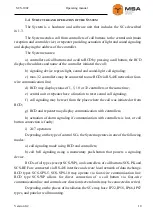
Страница 10: ...n to reset sound call signaling f call signaling may be reset from the place where the call was initiated or from RCD g RCD and repeater may display communication with controllers h actuation of alarm signaling if communication with controllers is lost or call button connection is faulty i 24 7 operation Depending on the type of control SCs the System operates in one of the following modes а call ...

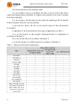
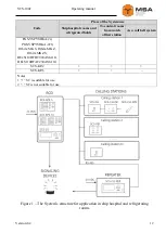
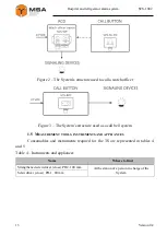
Страница 11: ...d be investigated Composition of the System depends on its type of application see table 3 а to use the System in ship hospital refrigerated holds or refrigerators in accordance with figure 1 b to call a watch officer in accordance with figure 2 c to use the System as a call bell system in accordance with figure 3 Table 3 Options of the System composition Code Place of the System use Ship hospital...

Страница 12: ...s from watch officer station As a call bell system PGS VSPYSHKA 24 PGS VSPYSHKA 220 Orbita MK S Orbita MK Z Orbita MK ZS BExS110DFDC024AS1A1G BExS110DFAC230AS1A1G SCS КР 2 SCS КР 6 Notes 1 SC is suitable for use 2 SC is not suitable for use Figure 1 The System s structure for application in ship hospital and refrigerating rooms ...

Страница 13: ...s structure used as a call bell system 1 5 MEASUREMENT TOOLS INSTRUMENTS AND APPLIANCES Consumables and instruments required for the TS are represented in tables 4 and 5 Table 4 Instruments and appliances Name Where to find Strengthened screwdriver cross PH2 100 mm At the station of a person in charge of the System Screwdriver cross РH 1 80 mm ...

Страница 14: ... х 0 06 m To polish surfaces of the Product in case of paint coating damage 1 6 MARKING AND SEALING The System has a nameplate displaying name and serial number the Manufacturer s details The nameplate is located on the RCD casing The SCs have nameplates displaying serial number weight protection degree input voltage and power consumption The nameplates are located on the casings of the SCs Sealin...

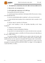
Страница 15: ...es sound signaling or resets call signaling depending on the design assignment f connection of external alarm g backlight of controls and brightness dimming h operation test of sound and light devices only units where test key is pressed i controls power supply to controllers of call buttons and repeater depending on the power supply scheme Two and more RCDs of SCS SPS type may operate within the ...

Страница 16: ...coming call 5 Brightness dimmer To adjust brightness of buttons backlight 6 Power LED To display power supply status 7 Piano type switch To switch on off power of RCD and connected external SCs 8 Speaker To provide sound call signaling 9 Test button To start operation test of LEDs Note Waterproof SCS SPS 5 type does not have a brightness dimmer RCD may set a timer of postponed sound signaling by m...

Страница 17: ...network c sound and light alarm signaling if communication with controllers of call buttons is lost d to control 32 controllers at the same time e to display status of 32 controllers their names and communication status on the LCD f to control RCD and provide its settings g temporary mute of sound call signaling and signaling of communication failure with a controller h to stop call signaling i to...

Страница 18: ...t button To provide temporary mute of sound signaling 5 Speaker To provide sound call signaling 6 Exit button To return to the previous level of menu until the main operating screen 7 Brightness control To adjust backlight brightness of controls and LCD 8 Menu key To access the menu When SCS CU is switched on LCD displays information on the status of controlled devices The stations are represented...

Страница 19: ... with constant glowing of the area and for the modes of lost connection the frame of the area remains highlighted with red Once the call is reset or connection with the controller or call button is restored corresponding area returns to the normal mode 2 1 3 Reception and control device SCS WP Functionality of SCS WP а to control signals from call buttons connected directly to RCD b to initiate al...

Страница 20: ...g on a standby watch station when a call signal from a controller occurs in the data exchange network The unit is recommended for additional control of calls from call buttons and or work of RCD operator The unit functions as RCD repeater with an option to mute local sound call signaling Note The unit may be used as a repeater of RCD in repeater mode The unit has the same functionality and outfitt...

Страница 21: ...and connection with RCD 2 2 1 Controllers of call buttons SCS CH Controllers of call buttons are designed to connect one or two external call buttons located within reach of a user For the exterior of SCS CH see figure 8 For the description and assignment of controls and LEDs see table 10 Figure 8 Exterior of SCS PK Table 10 Controls and LEDs of SCS PK Pos Name Description 1 Plastic slot To put an...

Страница 22: ...of SCS REF Table 11 Controls and LEDs of SCS REF Pos Name Description 1 Status LED To display the controller s status operation fault faulty communication line 2 Plastic slot To put an insert with a name of the station 3 Power LED To indicate that power is available 4 Reset button To reset a call 5 Call button with LED To make a call and display the initiate call 2 3 CALL BUTTONS The System includ...

Страница 23: ...ling unit IP code Note Call Reset SCS CH PB IP22 SCS BPT IP56 Heatproof SCS BPC IP56 Momentary push button SCS SC DC IP56 SCS CH EPB IP56 SCS SH DC IP22 Latching switch Note 1 SCS SH DC button is designed to repeat a call from an external call button until reset by a local button 2 functional element is available 3 functional element is not available ...

Страница 24: ...fore disconnecting cables replacement of fuses units or modules follow The technical rules for operation of electric installation and Safety rules for operation of electric installation while testing electrical circuits and insulation resistance After unpacking observe the System visually and make sure there is no mechanical damage of the components 3 2 2 Visual check procedure Before switching th...

Страница 25: ...low to set up RCD except SCS WP set up or reset a password except SCS SPS set up a reset timer 20 to 80 sec set up a quantity of controlled calling stations set up a name and background type of the station set up a timer of postponed sound signaling set up an operation mode of reset button reset or mute c provide settings of SCS WP set up an operation mode of reset button reset or mute d provide s...

Страница 26: ...med at the Manufacturer s plant if the System is delivered according to the technical design assignment of the customer or design company 3 2 5 System installation Perform installation of the System according to outline and installation dimensions While installing please pay attention to applied communication interface and limits of cable length for RS 485 up to 100 m All cables to connect the SCs...

Страница 27: ... 65 direct 1500 To connect RCD to a power supply unit power 24 V alternating 1000 200 50 to 65 direct 1500 3 3 INTENDED USE 3 3 1 The System with RCD To make a call press Call button on SCS CH PB SCS CH EPB SCS BPT SCS SC DC SCS REF Once the call is initiated call signaling actuates on RCD types SCS SPS 5 SCS SPS 10 SCS CU SCS WP and SCS CU REP and corresponding units actuate local signaling To re...

Страница 28: ...n the SC cycle of three brightness levels day evening night by brightness keys on SCS CU SCS CU REP rotation of brightness dimmer clockwise to increase brightness and counter clockwise to decrease brightness on units SCS WP and SCS SPS Note Set out brightness levels of three modes day evening night in the settings of SCs Operation test of LEDs controls backlight and sound signaling is carried out ...

Страница 29: ...st operation of indication and alarm press and hold a brightness key for more than 5 sec Once the test starts backlight brightness of controls and display will change from the maximum level to minimum and vice versa sound signaling actuates at the same time After the test RCD returns to normal operation ...

Страница 30: ...m The results of ТS 1 are registered in the operator s log book The results of ТS 2 are registered in the System s certificate Table 5 describes recommended quantity of consumables to perform TS 4 2 SAFETY FEATURES While maintaining the TS observe instructions in 5 2 of this operating manual 4 3 MAINTENANCE ROUTINE Table15 describes the list of works for all types of TS For information on maintena...

Страница 31: ...d cloth cover with varnish АК 113 and dry up 1 person 10 minutes Check cable and grounding bus connections Check that connectors and mounting screw are fastened tight provide further fastening if needed Check integrity of no mechanical damage the cables 1 person 5 minutes Table 17 CL 2 Function test of the SC To be done Routine Man hours per 1 SC Test functionality of the System Turn the System s ...

Страница 32: ...ble SPTA kit shall comply with the SPTA kit list 4 5 PRESERVATION The System and set of operational documents are stored in preserved condition in Manufacturer s packaging boxes The preservation is done in full terms for two years applying protection and packaging The represervation is done in heated rooms The represerved System SPTA kit and documents are placed in package The time of the Systems ...

Страница 33: ...ly circuit breaker breaker in OFF position Replacing damaged parts boards modules is PROHIBITED if power supply of the repaired unit is on Installation aligning and repair works are PROHIBITED in the room where less than 2 people are present 5 3 CURRENT REPAIR Own personnel may provide troubleshooting as specified in table 19 All other faults shall be eliminated only by the Manufacturer s speciali...

Страница 34: ...age conditions 5 С to 40 С with the concentration of dust oil moisture and aggressive impurities in the air within the required limits for the working areas of production facilities After storage or transportation of the System below 10 С it must be unpacked only in heated premises and left in normal climate conditions for 12 hours beforehand ...

Страница 35: ...transportation in sealed and heated compartments c sea transportation in dry service premises The System must be transported in compliance with the transportation rules applicable for each means of transport During loading unloading operations and transportation the requirements indicated on warning labels on the boxes packaging must be observed and no impacts are permitted since they can affect t...

Страница 36: ...also send an overage equipment unit to the manufacturer for its further disposal Proper disposal of the System components allows avoiding possible negative environmental and health impacts and it also allows for proper restoration of components with substantial energy and resources saving During operation and upon completion of its service life the equipment is not hazardous for health and environ...

Страница 37: ...urer will not consider damage claims in case of case violation of operating conditions More information about warranty terms you can find on the official website of NPK MSA LLC section Support Address and contacts of the Manufacturer s service centre NPK MSA LLC 26E Kibalchicha str 192174 St Petersburg Russia Tel 7 812 602 02 64 8 800 100 67 19 fax 7 812 362 76 36 e mail service unicont com ...

Страница 38: ...ECTION OF THE SYSTEM COMPONENTS Figure А 1 Connection of SCS SPS 5 SCS KP 6 SCS REF FL 24 Note The System may include junction boxes SCS KP 2 or SCS KP 6 from the System s scope of delivery and third party junction boxes that split cables to several outputs ...

Страница 39: ...re А 2 Connection of SCS CH PB SCS CH PB Ех and SCS BPT to controller SCS WP and signaling device with power supply 220 V to SCS REF Figure А 3 Connection of SCS WP power supply unit PS 103 and call button SCS SC DC Figure А 4 Connection of signaling devices to SCS BPC ...

Страница 40: ...Version 0 2 40 SCS 1002 Operating manual Figure А 5 Connection of several SCS SPS 5 by means of SCS KP 6 ...

Страница 41: ...41 Version 0 2 SCS 1002 Hospital and refrigerator alarm system Figure А 6 Connection of SCS SPS 5 SCS CU SCS CU REP controller SCS WP call buttons SCS CH PB SCS SH DC signaling device FL 24 ...

Страница 42: ...Version 0 2 42 SCS 1002 Operating manual Figure А 7 Connection of SCS SPS 10 SCS CU REP PS 103 call buttons SCS CH PB and controller SCS WP by means of junction box SCS KP 6 ...

Страница 43: ... 2 SCS 1002 Hospital and refrigerator alarm system Figure А 8 Connection of SCS SPS 10 SCS CU PS 103 signaling devices with power supply 24 V call buttons SCS CH PB and SCS CH EPB by means of junction box SCS KP 2 ...

Страница 44: ...SCS 1002 Operating manual Figure А 9 Connection of flashing lamp RL 24 and RL 220 types Figure А 10 Connection of flashing lamp RFL 24 and RFL 220 types Figure А 11 Connection of signaling devices L 24 and L 220 types ...

Страница 45: ...1002 Hospital and refrigerator alarm system Figure А 12 Connection of light signaling unit Orbita MK S Orbita MK Z and Orbita MK SZ Figure А 13 Connection of sound signaling units BExS110DFDC024AS1A1G BExS110DFAC230AS1A1G ...

Страница 46: ...Version 0 2 46 SCS 1002 Operating manual Figure А 14 Connection of light signaling units PGS VSPYSHKA 24 PGS VSPYSHKA 220 ...

Страница 47: ...rsion 0 2 SCS 1002 Hospital and refrigerator alarm system APPENDIX B DESCRIPTION AND PURPOSE OF THE SYSTEM COMPONENTS SCS SPS 5 wall mounting w casing SCS SPS 5 panel mounting w o casing SCS SPS 5 waterproof ...

Страница 48: ...ly muted connection of external alarm circuit brightness dimming self test function power control of controllers Technical specifications input voltage 24 V DC power consumption max 15 W communication method network RS 485 four wire communication line controlled units max 5 pcs operating temperature 15 С to 55 С protection degree IP22 IP56 if panel mounted only front panel weight SCS SPS 5 w o cas...

Страница 49: ...wer and status indication sound call signaling may be temporarily muted connection of external alarm circuit brightness dimming self test function power control of controllers Technical specifications input voltage 24 V DC power consumption max 15 W communication method network RS 485 or four wire communication line controlled units max 10 pcs operating temperature 15 С to 55 С protection degree I...

Страница 50: ...Version 0 2 50 SCS 1002 Operating manual SCS CU PM SCS CU WM ...

Страница 51: ...indication of connection faulty connection with controllers sound call signaling may be temporarily muted power control of controllers self test function connection of external alarm circuit Technical specifications input voltage 24 V DC power consumption max 5 W communication method network RS 485 controlled units max 32 operating temperature 15 С to 55 С protection degree SCS CU PM IP22 SCS CU W...

Страница 52: ...Version 0 2 52 SCS 1002 Operating manual SCS CU REP PM SCS CU REP WM ...

Страница 53: ...ndicates connection status with controllers of call buttons and actuates alarm if connection is faulty sound call signaling may be temporarily muted self test function connection of external alarm circuit Technical specifications input voltage 24 V DC max power consumption 5 W communication method RS 485 network controlled units max 32 operating temperature 15 С to 55 С protection degree IP22 weig...

Страница 54: ...m if call button connection is faulty sound call signaling may be temporarily muted self test of LEDs and sound signaling connection of external alarm circuit Technical specifications input voltage 24 V DC max power consumption 1 W controlled units 1 communication method four wire communication line protection degree IP56 operating temperature 40 С to 55 С weight 1 08 kg Mounting type wall ...

Страница 55: ...igerated holds connection of external alarm circuit call signaling stops when a corresponding button is pressed indication power status status of RCD communication Technical specifications input voltage 24 V DC max power consumption 2 W communication method with RCD RS 485 network operating temperature 40 С to 55 С protection degree IP56 weight 0 52 kg Mounting type wall ...

Страница 56: ...ction of two external call buttons initiates alarm if call button connection is faulty call reset button connection of external alarm circuit indication power status status of RCD communication Technical specifications input voltage 24 V DC max power consumption 2 W communication method with RCD network RS 485 operating temperature 15 С to 55 С protection degree IP22 weight 0 41 kg Mounting type w...

Страница 57: ...H PB Description The unit sends a call to a controller of call buttons Features connection of external hand held button SCS CH EPB indicates a call and power status Technical specifications operating temperature 15 С to 55 С protection degree IP22 weight 0 38 kg Mounting type wall ...

Страница 58: ...controller of call buttons Features connection of an external call button via four wire communication line indication of call and power status may be used under high ambient temperature Technical specifications operating temperature 40 С to 125 С protection degree IP56 weight 0 4 kg Mounting type wall ...

Страница 59: ...all and resets it via four wire communication line Features connection of an external call button via four wire communication line connection of external alarm circuit indication of call and power status Technical specifications operating temperature 40 С to 55 С protection degree IP56 weight 0 58 kg Mounting type wall ...

Страница 60: ...Version 0 2 60 SCS 1002 Operating manual SCS BPC wall mounting w casing SCS BPC panel mounting w o casing ...

Страница 61: ...power status quantity of connected signaling devices may be increased if SCS KP 2 or SCS KP 6 junction boxes are used Technical specifications connected alarm units 1 input voltage 24 V DC 220 V AC frequency 50 Hz max switching current 10 А operating temperature 40 С to 55 С protection degree IP56 if panel mounted only front panel weight 0 5 kg w casing Mounting type wall panel ...

Страница 62: ...rnal call button and controls signaling units Features used only with an external call button indication of call power status and status of communication line connection of external alarm circuit Technical specifications operating temperature 15 С to 55 С protection degree IP22 weight 0 65 kg Mounting type wall ...

Страница 63: ...tion the unit sends a call via four wire communication line Features used with call button SCS CH PB outfitted with 3 m cable and connector for SCS CH PB call button Technical specifications operating temperature 40 С to 55 С protection degree IP56 weight w cable 0 31 kg Mounting type hand held ...

Страница 64: ...itted with terminals to power the connected SCs Features RS 485 inputs 1 pc RS 485 outputs 2 pcs power inputs 1 pc power outputs 2 pcs Technical specifications switching current power circuits 15 А signaling circuits 2 А max switching voltage 250 V operating temperature 40 С to 55 С protection degree IP56 weight 0 93 kg Mounting type wall ...

Страница 65: ...65 Version 0 2 SCS 1002 Hospital and refrigerator alarm system SCS KP 6 IP22 type SCS KP 6 IP56 type ...

Страница 66: ...ls to power the connected SCs Features RS 485 inputs 1 pc RS 485 outputs 6 pcs power inputs 1 pc power outputs 6 pcs Technical specifications switching current power circuits 15 А signaling circuits 2 А max switching voltage 250 V operating temperature 15 С to 55 С protection degree IP22 or IP56 weight type IP22 1 10 kg type IP56 1 65 kg Mounting type wall ...

Страница 67: ...ith control signal Light and sound signaling units may be connected power 220 V or 24 V Technical specifications input voltage RB 139 220 220 V AC frequency 50 Hz RB 139 24 24 V DC max switching current 8 А outputs 2 pcs control signal dry contact protection degree IP56 weight RB 139 24 0 44 kg RB 139 220 0 45 kg operating temperature 40 С to 55 С Mounting type wall ...

Страница 68: ... incandescent RL 220 dome colours green RL 24 G RL 220 G red RL 24 R RL 220 R blue RL 24 B RL 220 B orange RL 24 О RL 220 О rotating Technical specifications input voltage RL 24 24 V DC RL 220 220 V AC frequency 50 Hz power RL 220 40 W RL 24 70 W rotation rate 180 rotations per minute operating temperature 40 С to 55 С protection degree IP56 weight RL 24 1 25 kg RL 220 1 50 kg Mounting type wall o...

Страница 69: ...tures dome colours green FL 24 G red FL 24 R blue FL 24 B orange FL 24 О delivered with a bracket and 3 m cable Technical specifications input voltage 18 to 36 V DC power consumption 3 W flashing rate 75 times per minute lamp type xenon brightness 26 cd protection degree IP56 operating temperature 40 С to 55 С weight 0 32 kg Mounting type wall on a bracket ...

Страница 70: ...d RFL 24 R RFL 220 R blue RFL 24 B RFL 220 B orange RFL 24 О RFL 220 О delivered with a bracket and 3 m cable Technical specifications input voltage RFL 24 24 V RFL 220 220 V power RFL 24 4 W RFL 220 10 V flashing rate 60 to 80 times per minute rotation rate 120 to 140 rotations per minute protection degree IP56 operating temperature 40 С to 55 С weight RFL 24 0 38 kg RFL 220 0 5 kg Mounting type ...

Страница 71: ...ith a standard knock out plug stamped casing for cable gland or cable inlet waterproof Technical specifications casing material plastic impact resistant power consumption A 24 0 6 W A 220 3 0 W input voltage A 24 24 V DC A 220 220 V AC frequency 50 Hz output signal frequency A 24 420 to 1200 Hz A 220 420 to 2900 Hz max sound pressure 100 dB operating temperature 40 С to 55 С protection degree IP56...

Страница 72: ... AL 24 W AL 220 W green AL 24 G AL 220 G red AL 24 R AL 220 R blue AL 24 B AL 220 B orange AL 24 О AL 220 О lamp type xenon waterproof Technical specifications casing material plastic impact resistant power AL 24 6 6 W AL 220 11 0 W input voltage AL 24 24 V DC AL 220 220 V AC frequency 50 Hz operating temperature 40 С to 55 С protection degree IP56 weight 0 43 kg Signals characteristics frequency ...

Страница 73: ...e outfitted with a standard knock out plug stamped casing for cable gland or cable inlet dome colours white L 24 W L 220 W green L 24 G L 220 G red L 24 R L 220 R blue L 24 B L 220 B orange L 24 О L 220 О waterproof Technical specifications casing material plastic impact resistant power L 24 7 5 W L 220 8 5 W input voltage L 24 24 V DC L 220 220 V AC frequency 50 Hz operating temperature 40 С to 5...

Страница 74: ...osion hazardous areas Features connection through cable gland or conduit stainless steel dome guard explosion proof waterproof Technical specifications power 14 W input voltage PGS VSPYSHKA 24 24 V DC PGS VSPYSHKA 220 220 V AC frequency 50 Hz operating temperature 40 С to 55 С protection degree IP66 weight 2 3 kg Mounting type wall ...

Страница 75: ...aling unit ORBITA MK S Description the unit ensures light call signaling in explosion hazardous areas Features explosion proof waterproof Technical specifications input voltage 24 V DC operating temperature 40 С to 55 С protection degree IP67 weight 1 5 kg Mounting type wall ...

Страница 76: ...ORBITA MK Z Description the unit ensures sound call signaling in explosion hazardous areas Features explosion proof waterproof Technical specifications input voltage 24 V DC operating temperature 40 С to 55 С protection degree IP67 weight 1 5 kg Mounting type wall ...

Страница 77: ...naling unit ORBITA MK SZ Description the unit ensures sound and light call signaling in explosion hazardous areas Features explosion proof waterproof Technical specifications input voltage 24 V DC operating temperature 40 С 55 С protection degree IP67 weight 1 5 kg Mounting type wall ...

Страница 78: ...xplosion proof waterproof customized signal tone Technical specifications input voltage BExS110DFDC024AS1A1G 24 V DC BExS110DFAC230AS1A1G 220 V AC 50 Hz operating temperature 40 С to 55 С power BExS110DFDC024AS1A1G 6 W BExS110DFAC230AS1A1G 12 W Output signal frequency 420 to 2900 Hz sound pressure 117 dB protection degree IP67 weight 3 2 kg Mounting type wall ...

Страница 79: ...B Ех Description the unit ensures a call in explosion hazardous areas Features explosion proof waterproof controls and LEDs Technical specifications input voltage 24 V DC power consumption max 2 W operating temperature 15 С to 55 С protection degree IP66 weight 8 kg Mounting type wall ...

Страница 80: ...Version 0 2 80 SCS 1002 Operating manual FOR NOTES ...

Отзывы: