Version 0.2
22
SCS-1002
Operating manual
2.2.2
Controllers of call buttons SCS-REF
To make a call, press
Call
button located on the controller. For the exterior of
the unit, see figure 9. For the description and assignment of controls and LEDs, see
table 11.
Figure 9 – Exterior of SCS-REF
Table 11 – Controls and LEDs of SCS-REF
Pos.
Name
Description
1
Status
LED
To display the controller’s status (operation, fault, faulty
communication line)
2
Plastic slot
To put an insert with a name of the station
3
Power
LED
To indicate that power is available
4
Reset
button
To reset a call
5
Call
button with LED
To make a call and display the initiate call
2.3
C
ALL BUTTONS
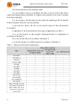
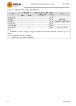
The System includes various types of call buttons with various functionality, see
table 12.
Содержание SCS-1002
Страница 40: ...Version 0 2 40 SCS 1002 Operating manual Figure А 5 Connection of several SCS SPS 5 by means of SCS KP 6 ...
Страница 50: ...Version 0 2 50 SCS 1002 Operating manual SCS CU PM SCS CU WM ...
Страница 52: ...Version 0 2 52 SCS 1002 Operating manual SCS CU REP PM SCS CU REP WM ...
Страница 60: ...Version 0 2 60 SCS 1002 Operating manual SCS BPC wall mounting w casing SCS BPC panel mounting w o casing ...
Страница 65: ...65 Version 0 2 SCS 1002 Hospital and refrigerator alarm system SCS KP 6 IP22 type SCS KP 6 IP56 type ...
Страница 80: ...Version 0 2 80 SCS 1002 Operating manual FOR NOTES ...


